Bicycle chain

A bicycle and chain technology, applied in the direction of chain rings, transmission chains, vehicle parts, etc., can solve the problem of inconvenience for cyclists

Active Publication Date: 2015-11-11
SHIMANO INC
View PDF6 Cites 12 Cited by
  • Summary
  • Abstract
  • Description
  • Claims
  • Application Information

AI Technical Summary

Problems solved by technology

This axial movement is greatest at position LE, which may cause the chain 120 to drop undesirably from the front sprocket 160, thereby causing inconvenience to the rider.

Method used


Image

  • Bicycle chain
  • Bicycle chain
  • Bicycle chain

Examples


Embodiment Construction

[0046] Selected embodiments will now be described with reference to the accompanying figures. It will be readily apparent to those skilled in the art from this disclosure that the following descriptions of the embodiments of the invention are for illustration only and not for the purpose of limiting the invention as defined by the appended claims and their equivalents.

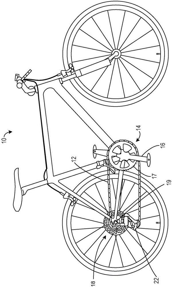
[0047] first reference figure 2 , illustrates an exemplary embodiment of a bicycle 10 . The bicycle 10 uses a bicycle chain 12 . Bicycle 10 includes, among other things, a drive train 14 configured to convert a rider's pedaling force into propulsion to propel the bicycle along a surface, such as a road or trail. Chain 12 is included in drive train 14 . The driveline 14 also includes a front chainring 16 , a rear sprocket assembly 18 and a rear derailleur 22 . Rear sprocket assembly 18 may also be referred to as a rear sprocket set.

[0048] The front chainring 16 is mounted on the bottom bracket in the s...


PUM


Abstract

An inner link plate for a bicycle chain is provided. The inner link plate may have a longitudinal centerline defining a longitudinal direction and comprising a first inner-link end portion including a first inner-link opening having a first inner-link center axis, a second inner-link end portion including a second inner-link opening having a second inner-link center axis parallel to the first inner-link center axis, and an inner-link intermediate portion interconnecting the first inner-link end portion and the second inner-link end portion. The first inner-link end portion may have an extended edge portion extending to be away from the second inner-link end portion in the longitudinal direction.

Description

technical field [0001] The present disclosure generally relates to bicycle chains. More specifically, the present invention relates to inner link plates for bicycle chains. Background technique [0002] Cycling is becoming an increasingly popular form of recreation and mode of transportation. Additionally, cycling has become a very popular competitive sport for both amateurs and professionals. Whether the bicycle is used for recreation, transportation or competition, the bicycle industry is constantly improving the various components of the bicycle. One component that has been redesigned is the bicycle chain. Most bicycles have a drive train that uses a chain to transmit the pedaling action from the rider to the rear wheel. A bicycle chain has a plurality of inner links and a plurality of outer links interconnected in an alternating fashion by a plurality of pins. Typically, each of the inner chains includes a pair of parallel inner plates connected by a pair of paralle...

Claims


Application Information

Patent Timeline
Patent Type & Authority Applications(China)
IPC IPC(8): F16G13/07F16G15/12B62M9/06
CPCF16G15/12B62M9/00B62M2009/005F16G13/06B62M9/06F16G13/07F16G15/14
Inventor 福森毅西本裕辅江村笃裕
Owner SHIMANO INC
Why Eureka
Try Eureka