Metering valve and metering method
A metering method and metering valve technology, applied in the field of metering valves, can solve problems such as poor metering results and inaccurate spraying of dosing materials, and achieve the effect of fine and accurate metering results
Active Publication Date: 2015-11-11
VERMES MICRODISPENSING GMBH
9 Cites 12 Cited by
AI-Extracted Technical Summary
Problems solved by technology
A too high impact velocity on the target surface due to too high an acceleration originating from the nozzle means that...
Method used
[0132] The motion profile shown in FIG. 11 differs from the motion profile shown in FIG. 10 again only in the ejection mode M5. In this case, the movement pattern in the first movement pattern M1 , ie the oscillating movement of the outlet opening 21 , is simply superimposed on the movement pattern during the ejection m...
Abstract
The present invention relates to a metering valve (1) for metering material to be metered, comprising: a valve chamber (33) having an outlet opening (21); a closure element (3) arranged in or on the valve chamber (33); a valve chamber bearing (23); and an actuator device (7), in order to move at least the outlet opening (21), preferably the valve chamber (33), in relation to the valve chamber bearing (23) in an ejection direction (E) and/or a retraction direction (R) in operation such that in operation material to be metered is pushed through the outlet opening (21) by the plunger (3) in at least one movement mode if there is a movement of the outlet opening (21) in the ejection direction (E). The invention further relates to a metering method that can be performed by means of such a metering valve (1).
Application Domain
Liquid surface applicatorsOperating means/releasing devices for valves +6
Technology Topic
ActuatorMetering mode +1
Image
Examples
- Experimental program(1)
Example Embodiment
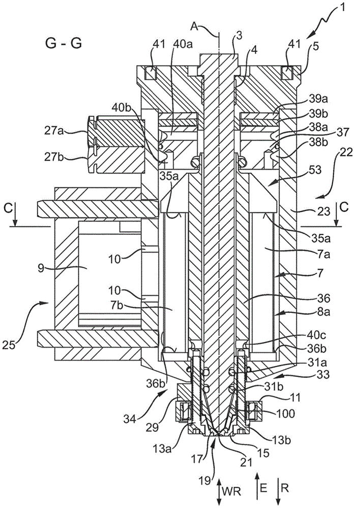
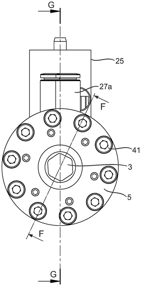
[0105] Figure 1 to Figure 6 A metering valve 1 according to an embodiment of the invention is shown in different full and detailed views, wherein, figure 1 and Image 6 shows along figure 2 Sectional view of the cut line G-G or F-F in, and basically refer to both views.
[0106] The metering valve 1 comprises a valve chamber 33 with a nozzle 19 and a valve housing 22, outside the valve chamber 33 an actuator chamber 53 is provided. The valve housing 22 comprises a lower first housing part 23 and an upper second housing part 5 in the form of a cover 5 . The two housing parts 5 , 23 are connected to each other by means of fastening bolts 41 .
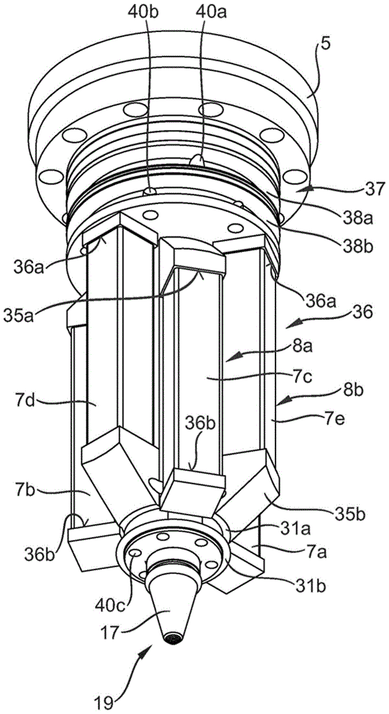
[0107] The actuator chamber 53 is arranged centrally in the valve housing 22 . Below the cover 5, a first piezoelectric actuator 8a and a second piezoelectric actuator 8b are connected via disc springs 39a, 39b and a movably mounted support body 37 (ie, support mass) (see Image 6 ) is oriented in the direction of the (middle) axis A and is positioned in the direction of the axis A. The piezoelectric actuators 8 a , 8 b together form the actuator 7 . The first piezoelectric actuator 8a includes three first piezoelectric actuator elements 7a, 7b, 7c, and the second piezoelectric actuator 8b includes three second piezoelectric actuator elements 7d, 7e, 7f. The arrangement and operation of these piezoelectric elements 7a, 7b, 7c, 7d, 7e, 7f will be image 3 and Figure 4 Details are described in the related embodiments.
[0108] In the valve housing 22 a valve chamber 33 is mounted coupled between the actuator elements 7a, 7b, 7c, 7d, 7e, 7f. The exact geometry of the valve chamber 33 and the coupling to the actuator elements 7a, 7b, 7c, 7d, 7e, 7f and the way the valve chamber 33 works will be discussed in relation to the Figures 5a to 5c Described in the relevant embodiment.
[0109] exist figure 1 Above the left-hand side of the middle, below the cover 5 , two compressed air connections 27 a, 27 b are provided on the lower housing part 23 . In addition, below the compressed air connections 27a, 27b there is mounted an electronics housing 25 including the control unit 9, which is electrically connected to the two piezoelectric actuators 8a, 8b by means of (not shown) electrical connection lines The piezo actuator is connected and controlled during operation of the metering valve, the electrical connection line being passed through the connection opening 10 into the valve housing 22 . The electronics housing is fastened to the valve housing 22 of the metering valve 1 , but it can also be removably mounted.
[0110] The valve chamber 33 here consists of two parts, namely the valve chamber head 34 in the region of the outlet opening 21 or in the fluid region of the metering valve 1 and in particular in the region of the actuator chamber 53 . the valve chamber base 36.
[0111] The nozzle 19 is equipped with a heating device 11 clamped thereon which can heat the nozzle 19 during operation. The nozzle 19 itself comprises a nozzle body 17 which tapers downwards in the figure and terminates in a discharge opening 21 . A nozzle cap 15 is mounted on the nozzle body (on the lower side in the figure), which connects the nozzle 19 with the valve chamber 33 by fixing bolts 13a, 13b. As a result, the nozzle body 17 is clamped firmly like a sandwich between the nozzle cap 15 and the valve chamber 33 and thus ultimately forms the lower closing part of the valve chamber 33 . The valve chamber head 34 is clamped between the nozzle cap 15 and the valve chamber base 36 .
[0112] On the valve housing 22 a fixed closing element 3 in the form of a plunger 3 is mounted in the center aligned along the axis A. The plunger 3 is connected to the valve housing 22 via a thread 4 in the cover 5 of the valve housing 22 . The plunger is guided through the actuator chamber 53 and here through the valve chamber 33 and can be screwed on by the cover 5 without opening the valve housing 22 . The outer shape of the plunger tapers downwards in the region of the nozzle 19, in fact similar to the inner shape of the nozzle body 17, where there is always a certain passage gap 100 between the nozzle body 17 and the plunger 3, So that the nozzle of the metering valve 1 is never completely closed to the outside.
[0113] The nozzles 19 are fed by a dosing substance delivery unit 29 which delivers a dosing substance (not shown) into the channel gap 100 through channels or openings (see 47a, 47b in FIG. 8). The dosed substance travels further through the channel gap 100 in the direction of the discharge opening 21 . In the region of the channel gap 100 , the “fluidic” part of the valve chamber 33 is functionally and fluidly connected to the upper “actuator region” of the valve chamber 33 located in the actuator chamber 53 by means of the two annular seals 31 a , 31 b separation, so that no dosing substance can reach the actuator area.
[0114] As already mentioned, in the metering valve according to the prior art, the closing element 3, ie the plunger 3, is moved in order to deliver the metered substance through the discharge opening. In contrast to this in the present invention, the movement of the closing element 3 is partially or completely replaced by the movement of the discharge opening 21 as in the present exemplary embodiment. This means that the actuating device 7 reciprocates the discharge opening 21 along the action direction axis WR by the movement of the valve chamber 33 . Here, the discharge port moves upward in the pushing direction E and moves downward in the retracting direction R. Here, the push-out direction E of the discharge port 21 refers to the movement direction in which the dosed substance is pushed out by the plunger 3 . That is, when the discharge port 21 moves in the push-out direction E, the dosed substance is pushed out by the plunger 3 through the discharge port 21 . In contrast, the plunger 3 is pulled back in the retraction direction relative to the forward movement away from the discharge opening 21 of the plunger 3 .
[0115] The two piezoelectric actuators 8a, 8b are arranged such that during operation they are deflected along the axis A essentially in the axial direction. The piezoelectric actuators 8a, 8b are piezoelectric stacks composed of rectangular piezoelectric elements. The two piezoelectric actuators 8a, 8b are connected in mirror images. This means that when the first piezoelectric actuator 8a reduces its overall length in the longitudinal direction (ie vertical direction), the second piezoelectric actuator 8b simultaneously increases its length in the same direction to the same extent. Conversely, when the first piezoelectric actuator 8a increases its overall length in the longitudinal direction, the second piezoelectric actuator 8b simultaneously reduces its length in the same direction to the same extent.
[0116] During operation of the metering valve 1, the electronic control unit 9 generates a first control signal and a second control signal, which are transmitted to the two piezoelectric actuators 8a, 8b and control the movement (ie deflection of the piezoelectric actuators) ). These control signals are designed to activate the two piezoelectric actuators 8a, 8b in contrast. This results in opposite movement patterns of the two piezoelectric actuators 8a, 8b. Through the movement of the first piezoelectric actuator 8a, which is operatively connected to the discharge port 21, the discharge port 21 is excited to perform lifting and advancing movements. That is, the second piezoelectric actuator 8b contracts while the first piezoelectric actuator 8a expands, so that the discharge port 21 is pressed in the push-out direction E by the first piezoelectric actuator 8a. During the reverse movement, the discharge port 21 is pushed downward in the retracting direction R by the second piezoelectric actuator 8b. That is, the axis WR of the two piezoelectric actuators 8 a , 8 b , which is here in the common direction of action, is oriented exactly like the extension direction E or the retraction direction R along the axis A. The indirect coupling of the actuator 7 formed by the actuator 8a and the second piezoelectric actuator 8b enables the outlet 21 to always be pushed in the desired direction by the respective stretched piezoelectric actuators 8a, 8b.
[0117] Via the compressed air connections 27a, 27b, compressed air can be introduced into the actuator chamber 53 and guided out there again. Therefore, the upper compressed air port 27a is used as the inlet port 27a, and the lower compressed air port 27b is used as the outlet port 27b. For the passage of compressed air, the support body 37 has two circumferential grooves 38a, 38b and passage holes 40a, 40b as cooling passages. Compressed air is introduced from the introduction port 27a into the interior of the upper part of the valve chamber 33 along the plunger 3 via the upper groove 38a and through the first (upper, horizontal) passage hole 40a corresponding thereto, and through The (horizontal) channel hole 40c in the valve chamber 33 (as another cooling channel) is fed further in the direction of the actuator 7 . The compressed air thus flows around the actuator elements 7a, 7b, 7c, 7d, 7e, 7f between the valve chamber 33 and the valve housing 22, and then through the second (upper, horizontal) of the support body 37 The passage hole reaches into the region of the second groove and from there into the outlet opening 27b. As a result, compressed air can circulate as a cooling medium in the region of the actuator chamber 53 of the valve housing 22 and in particular effectively cool the actuators 8a, 8b.
[0118] image 3 A perspective view is shown of selected parts of the metering valve 1 according to the invention, namely the valve chamber base 36 with the actuators 8a, 8b or actuator elements 7a, 7b, 7c, 7d, 7e, 7f. The actuator element 7f is hidden by the valve chamber base body 36 in this view. Furthermore, the carrier body 37 and the cover 5 are shown.
[0119] The actuator elements 7a, 7b, 7c of the first actuator 8a are supported on the bearing surface 36b at its lower part, ie at the end side in the direction of the discharge opening 21, and at its upper part, ie at the end side in the opposite direction. On the support surface 35a of the nose-shaped (ie inclined from the upper side) support body, which is fixedly connected to the valve chamber base body 36 or protrudes outwardly from the valve chamber base body 36 . Similarly, the actuator elements 7d, 7e, 7f of the second actuator 8b are supported at their lower part, ie at the end side in the direction of the discharge opening 21, on the support surface 35b of the corresponding nose-shaped support and at their upper part That is, the end side in the opposite direction is supported on the support surface 36a. The support body with the support surface 36 a is also fixedly connected to the valve chamber base body 36 or protrudes outwardly from the valve chamber base body 36 . Conversely, the upper abutment surface 36a (via the abutment body 37) is opposite the valve housing 22 (seefigure 1 and Image 6 ) is elastically supported so that when the actuator elements 7a, 7b, 7c of the first actuator 8a are stretched, the valve chamber base body 36 is moved upwards and thus indirectly also the outlet opening 21 in the push-out direction E. When the actuator elements 7d, 7e, 7f of the second actuator 8b are extended, the valve chamber base body 36 moves downwards and thus also moves the outlet in the retraction direction R indirectly.
[0120] like image 3 , Figure 4 and Figures 5a to 5c As shown, the actuator elements 7a, 7b, 7c, 7d, 7e, 7f are arranged radially about an axis A, which is at the same time the central axis A of the valve chamber element 45 . Each actuator 8a, 8b has three actuator elements 7a, 7b, 7c or 7d, 7e, 7f in each case, here the actuator elements 7a, 7b, 7c of the actuator 8a or the actuator element 7d of the actuator 8b , 7e, 7f are each offset relative to each other by 120° about the axis A, and the actuator elements 7a, 7b, 7c of the first actuator 8a always alternate with the actuator elements 7d, 7e, 7f of the second actuator 8b. This results in a star-shaped, uniform, rotationally symmetrical arrangement of the actuator elements 7a, 7b, 7c, 7d, 7e, 7f, wherein the actuator elements 7a, 7b, 7c of the first actuator 8a are also always connected to each other. The actuator elements 7d, 7e, 7f of the second actuator 8b are opposite with respect to the central axis A.
[0121] about Figure 5a and Figure 5b It should also be noted that the valve chamber base 36 is constructed as an integrated element. Here, the valve chamber base body has a main body 45 and a support body. The previously mentioned passage hole 40c is located in the lower part of the main body 45, approximately at the height of the lower third of the lower support.
[0122] In order to explain the working principle of the metering valve, Image 6 shown along the cut line F-F (see figure 2 ) of the second longitudinal cross-sectional view. Here, because of the cross-sectional perspective view, what is seen is not two actuator elements of the same actuator, but one actuator element of the first actuator 8a and one actuator element of the second actuator 8b, respectively . Furthermore, the dosing substance delivery unit 29 is shown here in section.
[0123] The metering valve 1 shown here can be assembled, for example, as follows: First, the piezoelectric actuator elements 7a, 7b, 7c, 7d, 7e, 7f are firmly glued to the valve chamber base body 36, on the bearing surfaces 35a, 36b. The piezoelectric elements 7a, 7b, 7c, 7d, 7e, 7f are then brought into electrical contact with the control unit 9. The unit consisting of the piezoelectric actuator elements 7a, 7b, 7c, 7d, 7e, 7f and 45 is then pushed into the valve housing 22, on which the support body 37 and the disc springs 39a, 39b are gradually pushed placed on the unit. The valve is then closed with the cover 5 , and finally the plunger 3 , which has a hexagonal design on the upper side, is screwed into the valve housing 22 via the thread 4 .
[0124] Figure 7a A side view of the nozzle cap 15 is shown, Figure 7b shows a view of the nozzle cap 15 from below (relevant to the figure 1 The metering valve 1) shown conventionally in Figure 7c A perspective view of the nozzle cap 15 is shown. The nozzle cap has an opening 49, for example at figure 1 The fixing bolts 13a, 13b shown in can pass through this opening. An opening is provided centrally in the middle, into which the nozzle body with the discharge opening 21 engages. By loosening the fixing bolts 13a, 13b, the nozzle cap 15 can be removed from the nozzle body 17 to expose the nozzle body, and for example for maintenance it is also necessary to remove the nozzle body from the metering valve 1 and use other nozzles as required body to replace.
[0125] As already mentioned, the metering valve 1 is designed as an open system in the embodiment shown here. Within the scope of the present invention, a specific movement pattern of the discharge opening 21 is particularly preferably realized here, which is explained in more detail below:
[0126] Figures 8a to 8d The nozzle body 17 is shown in several views, wherein, Figure 8a For the floor plan seen from below, Figure 8b for side view, Figure 8c is a cross-sectional view along the cutting line B-B, Figure 8d It is a perspective view seen from diagonally below.
[0127] In particular, in these views, extension holes 49 ′ can be seen, which are matched in position with the openings 49 of the nozzle cap 15 so that the fixing screws (for example in the figure 1 The fixing bolts 13a, 13b) shown in can be passed through the extension holes. Furthermore, the arrangement of the openings 47a, 47b can also be seen in the figure, through which openings the dosing substance reaches the channel gap 100 in the direction of the outlet opening 21 . The two openings 47a, 47b terminate on the outside in connecting openings 48a, 48b at which a connection to the dosing substance delivery unit 29 can be established. especially if Figure 8c As shown, these openings are not introduced centrally into the interior of the nozzle body 17 , but are provided on the sides, so that the openings and thus also the dosing substance are not centered at the inner center point of the nozzle body 17 , but are instead Pass by. As a result, for example, the dosing substance can be guided annularly in the region of the channel gap 100 , or the dosing substance can be swirled.
[0128] Figure 9 A possible movement profile of the outlet opening 21 is shown schematically in this connection. Therein is plotted the distance s (unscaled) of the outlet 21 with respect to time t (unscaled). Here it can be seen that the discharge port 21 performs three different movement modes M 1 , M 2 , M 3.
[0129] The first sport mode M 1 at zero time t 0 and the first time point t 1 between, the second time point t 2 and the third time point t 3 between, and the fourth time point t 4 and the fifth time point t 5 executed in between. The sport mode M 1 in two positions 1 , s 2 There is tiny, relatively fast oscillatory motion in between. That is, the movement of the discharge opening 21 has only a small amplitude A here. 1 or a smaller itinerary A 1 , and has a uniform rhythm and relatively high frequency. This movement serves only to maintain the fluidity of the dosing substance, but the dosing substance is not liquefied so strongly that the dosing substance can be continuously obtained from the nozzle 19 . Therefore, the first movement mode M 1 Can also be described as flow-preserving mode.
[0130] Second sport mode M 2 at the first point in time t 1 and the second time point t 2 Between, the third time point t 3 and the fourth time point t 4 between and the fifth time point t 5 and the sixth time point t 6 are performed in between, and conversely have another type of movement. This movement mode is used to push the dosed substance out of the discharge opening 21 and can therefore be referred to as the push-out mode. Therefore, this motion pattern has a larger amplitude A 2 or larger stroke A 2. Especially at the fifth time point t 5 and the sixth time point t 6 It can be seen in the two push-out movements between, the frequency of this movement mode is significantly lower than that of the first movement mode M 1 exercise frequency in . The rhythm of the movement can also be considered uniform. At the sixth time point t 6 The third movement mode M executed after 3 It consists of a simple resting state of the outlet 21 and results in the dosing substance in the channel gap 100 being first braked due to its internal friction and then stopped since its viscosity is no longer reduced by the movement of the outlet 21 .
[0131] Figure 10 The motion curve shown is the same as Figure 9 The motion profile shown differs only in the push-out mode M 4. different from Figure 9 The second sport mode M shown 2 In a simple zigzag up and down movement, the outlet 21 is now in the lower position s respectively 4 stop for a while. During this time, the dosing substance in front of the plunger 3 can continue to flow The discharge opening 21 then moves in the ejection direction E extremely rapidly. in the maximum upper position s 3 At the position closest to the plunger 3, the discharge port 21 will stop again for a period of time. During this time, the movement of the dosing substance is substantially stopped in order to avoid continued dripping of the dosing substance during the subsequent movement of the discharge opening 21 in the retraction direction R.
[0132] Figure 11 The motion curve shown is the same as Figure 10 The movement curves shown are still only differentiated by the launch mode M 5. Here, the first sport mode M is 1 The movement pattern in the Figure 9 Sport mode M shown 4 On the movement pattern during the push-out exercise. This makes sense for dosing substances whose viscosity rises again relatively quickly when the high-precision quivering movement is stopped. Through this superimposition of the modes of movement, the viscosity of the dosing substance can be continuously reduced.
[0133] at last, Figure 12 A movement curve is shown, which is suitable, for example, for drawing a “crawler” of uniform density, ie a continuous stripe, by arranging the individual points of the dosing substance in close proximity. Depending on the dosing substance, even if the same lift height is chosen for the discharge opening 21 for each droplet, it may happen that both the first droplet and the last droplet are larger than the droplet metered between them. In this case, it is appropriate to set different push-out modes M that differ from each other only in the lift height 2 , M 6. For example, a movement mode M with a smaller lift height can be selected for the first drop and the last drop, respectively, than for intermediate metered droplets 2.
[0134] These examples clearly show that, by means of the embodiment of the metering method according to the invention, the correct parameters of the individual motion modes and the sequence of these motion modes can ideally be adjusted precisely according to the individual dosing substance to be processed and the dosing task.
[0135]Finally, it should be pointed out once again that the above-specified components of the metering valve or metering system and actuating device relate only to exemplary embodiments, which can be modified in various ways by those skilled in the art without departing from the scope of the present invention. These components are modified or recombined with their characteristics. Thus, the outlet opening can not only be moved individually when the closing element is always stationary, but also the closing element can be moved temporarily. For this reason, although the closing element can be moved in the metering valve, only some movements other than the discharge port are performed selectively (based on control). It is also not necessary for the discharge opening to perform every movement in parallel with the (movable) closing element, but likewise can only be selectively moved, eg according to a selected (ie in particular programmed) movement pattern. The key point of the invention is that the discharge opening moves in at least one movement mode. Likewise, it is also possible, for example, to design the nozzle as a simple orifice, ie, instead of a device with a discharge opening and tapering towards the discharge opening, but a substantially flat device with a discharge area where the discharge Only the discharge openings are left empty in the region, and the discharge openings are likewise not tapered. Furthermore, although the indefinite articles "a" or "an" are used, it does not exclude that there may be a plurality of the referenced feature. In addition, a "unit" may also include one or more spatially distributed components.
PUM


Description & Claims & Application Information
We can also present the details of the Description, Claims and Application information to help users get a comprehensive understanding of the technical details of the patent, such as background art, summary of invention, brief description of drawings, description of embodiments, and other original content. On the other hand, users can also determine the specific scope of protection of the technology through the list of claims; as well as understand the changes in the life cycle of the technology with the presentation of the patent timeline. Login to view more.