A Synchronous Scanning Intersection Measurement Fusion Imaging System
What is AI technical title?
AI technical title is built by PatSnap AI team. It summarizes the technical point description of the patent document.
A technology of intersection measurement and imaging system, applied in the field of aerospace optical remote sensing, can solve the problems of low measurement accuracy of lidar, triangulation ranging measurement range and measurement accuracy can not adapt to different targets, poor anti-stray light performance, etc., to achieve smooth noise and The effect of burr, strong anti-stray light interference ability, and large measurement range
Active Publication Date: 2018-10-09
BEIJING INST OF CONTROL ENG
View PDF2 Cites 0 Cited by
Summary
Abstract
Description
Claims
Application Information
AI Technical Summary
This helps you quickly interpret patents by identifying the three key elements:
Problems solved by technology
Method used
Benefits of technology
Problems solved by technology
[0006] The technical problem solved by the invention is: to overcome the problems of poor anti-stray light performance of binocular vision measurement, low measurement accuracy of laser radar, and the measurement range and measurement accuracy of triangular distance measurement cannot adapt to different targets, and a fusion of binocular vision is proposed. The synchronous scanning intersection measurement system of lidar and triangular distance measurement can obtain the highest measurement accuracy of triangular distance measurement according to the horizontal size of the measured object and the maximum and minimum distance range of the surface, and at the same time meet the horizontal and vertical measurement range and measurement of the surface of the measured object. Accuracy requirements
Method used
Image
Click on the blue label to locate the original text in one second.
Reading with bidirectional positioning of images and text.
Examples
Embodiment
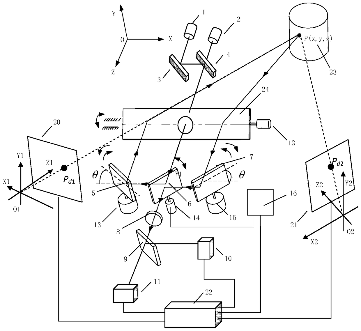
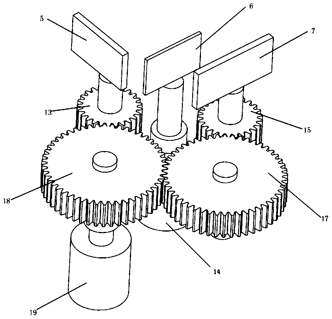
[0025] Continuous laser 1 adopts a continuous semiconductor laser model of LU0845M150 with a wavelength of 845nm and a power of 150mW; pulsed laser 2 adopts a pulsed fiber laser model of PYFL-K04-PK5D-FA with a wavelength of 1064nm, a peak power of 5kW, and a pulse width of 6ns The receiving lens 8 is an aspheric doublet lens of Edmund Company, and the focal length is 70mm; the line array camera 10 is a Baslarral4096-80km camera, the resolution is 1×4096, the highest sampling frequency is 80kHz, and the photosensitive surface length is 28.672mm; the photodetector 11 It is C30955EH-TC avalanche photodiode APD with cooling, the responsivity is 34A / W, the photosensitive surface size is 1.5mm; the left camera 20 and the right camera 21 are both BaslaracA2040_25gm area array cameras, the resolution is 2048×2048; double-sided reflection The mirror 6 forms an initial angle of 45° with the positive direction of the X-axis, and the left reflector 5 and the right reflector 7 are symmetri...
PUM
Abstract
A synchronous scanning intersection measurement fusion imaging system comprises a continuous laser (1), a pulse laser (2), a single reflector (3), a beam combination lens (4), a left reflector (5), a double-face reflector (6), a right reflector (7), a reception lens (8), a beam splitter lens (9), a linear array camera (10), a photoelectric detector (11), a Y-direction scanning servo motor (12), a left reflector gear (13), an X-direction scanning servo motor (14), a right reflector gear (15), a driving controller (16), a first transmission gear (17), a second transmission gear (18), a stepping motor (19), a left camera (20), a right camera (21), a data processing unit (22) and a bar-type reflector (24). The system fuses binocular vision, laser radar and triangular range measurement synchronous scanning intersection measurement, can obtain the highest measurement precision of triangular range measurement, and meanwhile, meets transverse and vertical measurement range and measurement precision requirement of a tested object.
Description
technical field [0001] The invention belongs to the field of aerospace optical remote sensing and relates to a rendezvous measurement system, which can be used to measure the three-dimensional surface shape of a target and obtain the position and attitude information of the target. Background technique [0002] 3D vision measurement technology has been widely used in various fields, such as industry, aviation, military and so on. In non-cooperative target intersection measurement, since the target does not have luminous markers or corner reflectors with prior structural information, the relative position and attitude of the target cannot be realized by shooting two-dimensional grayscale images, so it is necessary to obtain the target’s three-dimensional information. The mainstream 3D information acquisition technologies mainly include binocular stereo vision technology, laser radar technology and laser triangulation ranging technology. [0003] The measurement accuracy of ...
Claims
Application Information
Patent Timeline
Application Date:The date an application was filed.
Publication Date:The date a patent or application was officially published.
First Publication Date:The earliest publication date of a patent with the same application number.
Issue Date:Publication date of the patent grant document.
PCT Entry Date:The Entry date of PCT National Phase.
Estimated Expiry Date:The statutory expiry date of a patent right according to the Patent Law, and it is the longest term of protection that the patent right can achieve without the termination of the patent right due to other reasons(Term extension factor has been taken into account ).
Invalid Date:Actual expiry date is based on effective date or publication date of legal transaction data of invalid patent.

