Eureka AIR delivers breakthrough ideas for toughest innovation challenges, trusted by R&D personnel around the world.

Wire Clamp

A technology of wire clips and wires, which is applied in the installation of electrical components and cables, overhead installation, etc., and can solve problems such as weak shear strength, inability to exert clamping force, and damage to core materials

Active Publication Date: 2018-11-13
TOKYO ROPE MFG
View PDF8 Cites 0 Cited by
  • Summary
  • Abstract
  • Description
  • Claims
  • Application Information

AI Technical Summary

Problems solved by technology

Carbon fiber material has a high tensile strength or modulus of elasticity, but its shear strength is weak. If a strong squeeze that is usually used is applied when clamping a steel core wire, the carbon fiber material will be crushed and damaged, and thus the expected performance cannot be exerted. High clamping force, which breaks away the core material at low tension

Method used


Image

  • Wire Clamp
  • Wire Clamp
  • Wire Clamp

Examples


Embodiment Construction

[0026] [Best plan for implementing the invention]

[0027] Embodiments of the present invention will be described below with reference to the drawings.

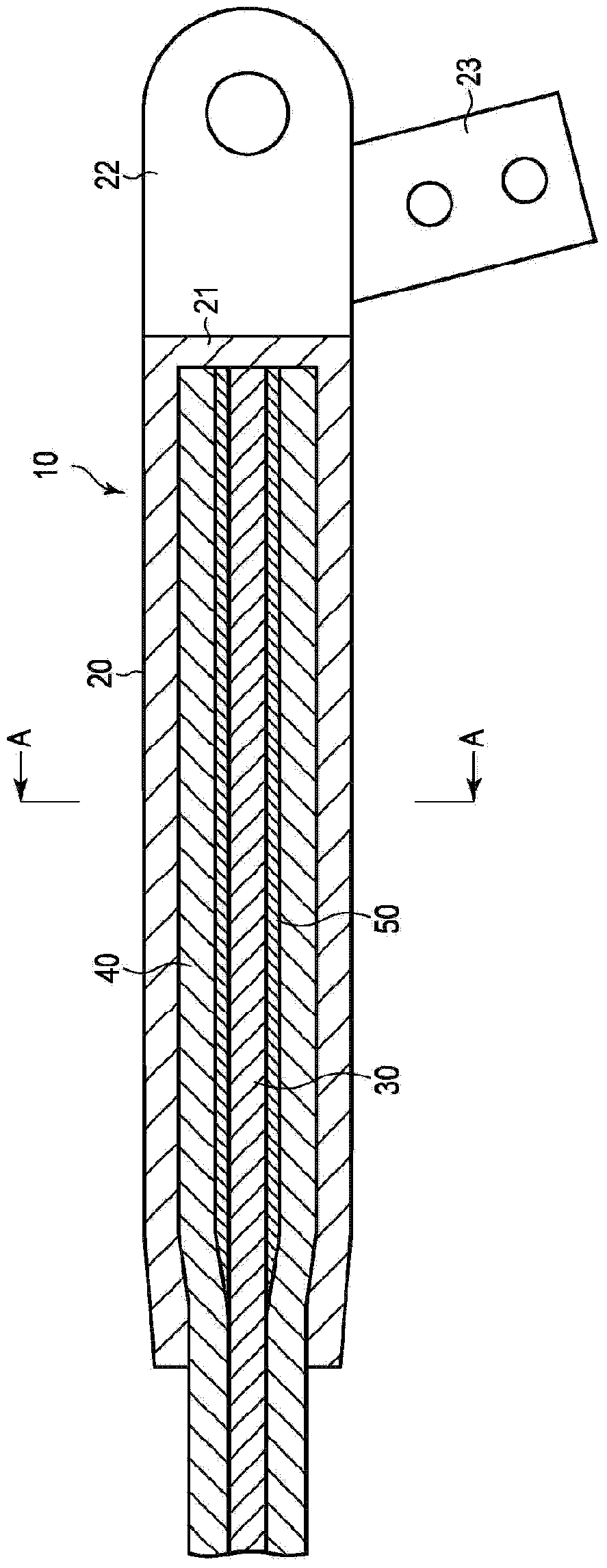
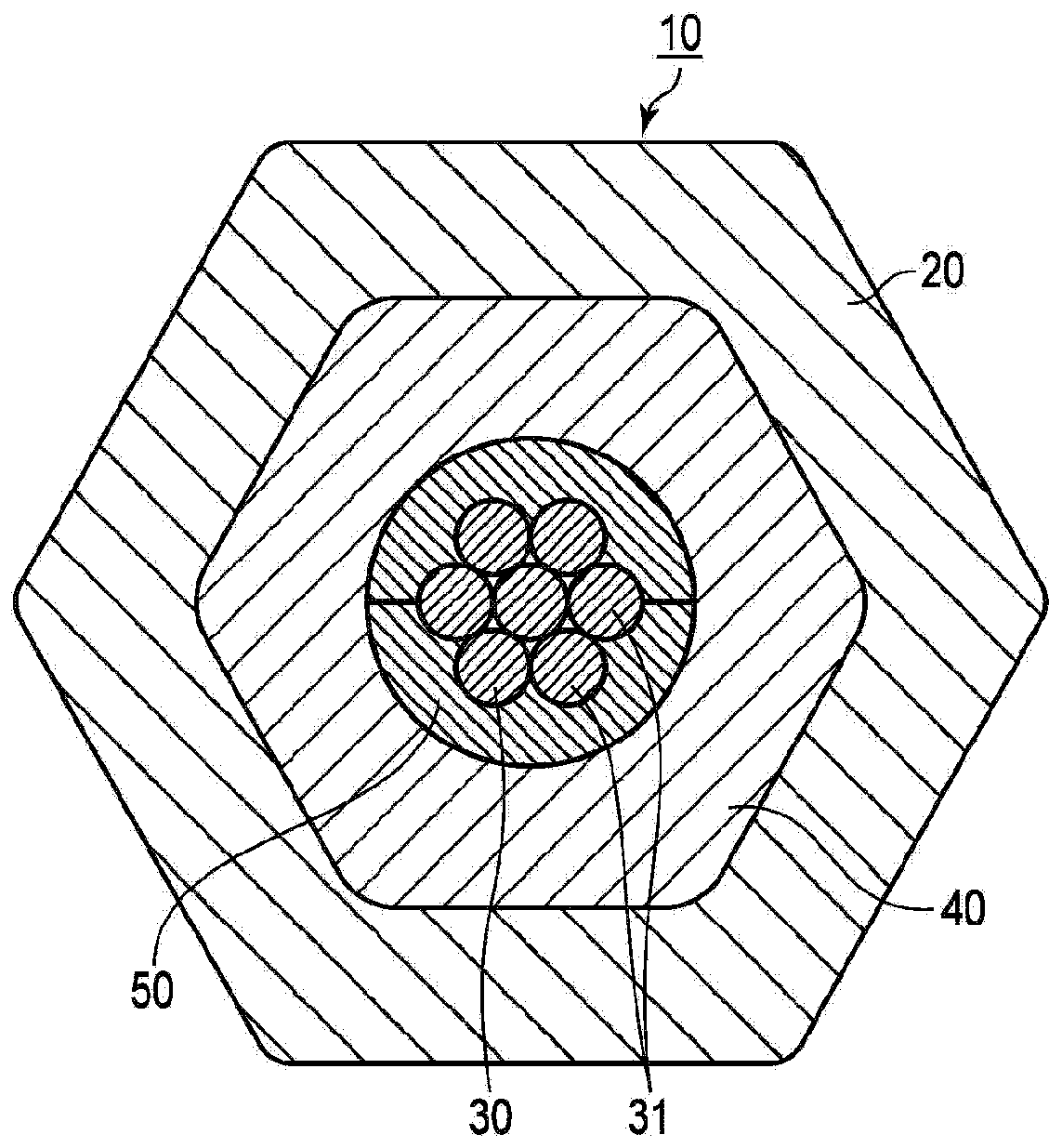
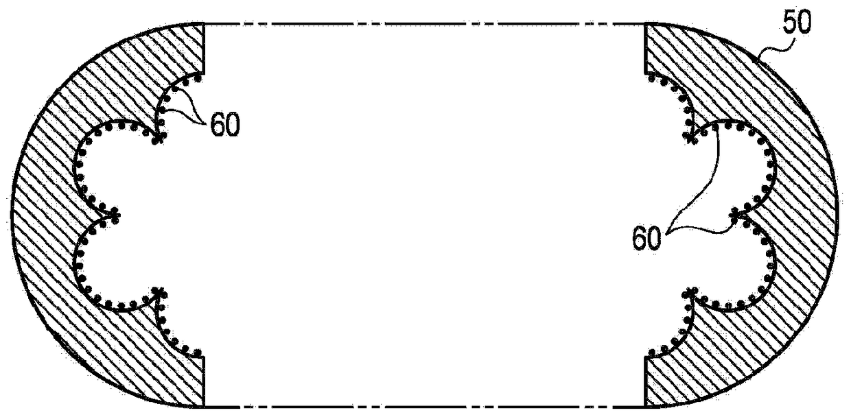
[0028] figure 1 is a longitudinal sectional view showing the integrated electric wire clamp 10 according to the first embodiment of the present invention, figure 2 is along figure 1 The A-A line cuts off the wire clamp and looks at the cross-sectional view from the direction of the arrow, image 3 is a cross-sectional view showing the metal cushioning material 50 assembled in the wire clamp 10, Figure 4 It is a perspective view showing the metal cushioning material 50 and the carbon fiber core material 30 assembled in the wire clamp 10 . In the description, the axial direction refers to the extending direction of the base wire 31 , which is the same direction as the pulling force generated on the base wire 31 . The electric wire clamp is a member for fixing the end of the electric wire, and it is necessary to have a me...


PUM


Abstract

A wire clamp provided by the invention is used for clamping an end part of a wire. The wire is provided with a carbon fiber core formed by twisting a basic line and an aluminum twisting line formed by being twisted with an aluminum line and arranged on the outer periphery of the carbon fiber core. The wire clamp is provided with wrapping fibers arranged on the outer periphery of the basic line and twisting in a direction perpendicular to a pulling force generated from the basic line; cylindrical metal buffer material which is inserted between the carbon fiber core and the aluminum twisted line and whose inner periphery is provided with bumps and pits corresponding to the wrapping fibers; rigid particles arranged on the inner periphery of the metal buffer material and containing at least one material of aluminum oxide and silicon carbide; and a cylindrical aluminum sleeve arranged on the outer peripheral side of the aluminum twisting line and used for fixing the aluminum twisting line, the metal buffer material and the carbon fiber core in an extruding manner. According to the invention, sufficient and stable clamping forces are realized by the simple structure.

Description

technical field [0001] The present invention relates to a wire clamp for use in positioning the ends of wires such as overhead wires. Background technique [0002] As a method of transmitting electric power to a remote place, overhead wires (hereinafter, referred to as "wires") in the form of overhead wires are used. This electric wire consists of a core material that bears a large amount of wiring tension, and aluminum wires twisted in multiple layers around the core material. Aluminum wires are excellent electrical conductors and are light in weight, so they are preferable as wires in the form of overhead wires. Steel strands are used as the core material, but carbon fiber materials that are light in weight, high in strength, and low in linear expansion are also used. By using carbon fiber material, compared with the case of using steel strands, the overall weight of the wire can be reduced, the tensile strength can be increased, the linear expansion can be reduced, the ...

Claims


Application Information

Patent Timeline
Patent Type & Authority Patents(China)
IPC IPC(8): H02G7/00
Inventor 蜂须贺俊次木村浩真锅太辅田村佳广
Owner TOKYO ROPE MFG
Why Eureka
Eureka Blog
Learn More