Eureka AIR delivers breakthrough ideas for toughest innovation challenges, trusted by R&D personnel around the world.

Crossbeam clamping mechanism used for heavy-duty crossbeam-elevating gantry machine tool

A technology of gantry machine tools and clamping mechanisms, which is applied in the direction of large fixed members, metal processing machinery parts, metal processing equipment, etc., can solve the inconvenience of maintenance of the sliding guide rail surface of the beam and the column guide rail, affect the repeated positioning accuracy of the machine tool, and not adapt Problems such as beam clamping requirements, to achieve stable and reliable detachable fixed connection, convenient and fast installation process, and low maintenance cost

Inactive Publication Date: 2018-03-27
SICHUAN UNIVERSITY OF SCIENCE AND ENGINEERING
View PDF7 Cites 5 Cited by
  • Summary
  • Abstract
  • Description
  • Claims
  • Application Information

AI Technical Summary

Problems solved by technology

However, this structure has a relatively large disadvantage: the clamping device is realized by the pressing force between the sliding guide rail surface of the machine tool beam and the column guide rail. The heavier the beam, the greater the pressing force required, and the greater the deformation of the beam and column. Deformation will affect the accuracy of repeat positioning of the machine tool. At the same time, it is inconvenient to maintain the sliding guide rail surface of the deformed beam and the column guide rail, which reduces its service life. It is also uneconomical to replace the deformed structure as a whole, which increases the equipment investment. Cost; especially for heavy-duty gantry machine tools with a beam weight of more than 50 tons, due to the huge pressing force, the pressing force acting on the beam and the guide rail surface of the column will cause a large compression deformation of the relatively weak beam, which is easier Affect the repeated positioning accuracy of the machine tool
Therefore, the above two commonly used beam compression structures are not suitable for the beam clamping requirements of heavy-duty beam lifting gantry machine tools

Method used


Image

  • Crossbeam clamping mechanism used for heavy-duty crossbeam-elevating gantry machine tool
  • Crossbeam clamping mechanism used for heavy-duty crossbeam-elevating gantry machine tool
  • Crossbeam clamping mechanism used for heavy-duty crossbeam-elevating gantry machine tool

Examples


Embodiment 1

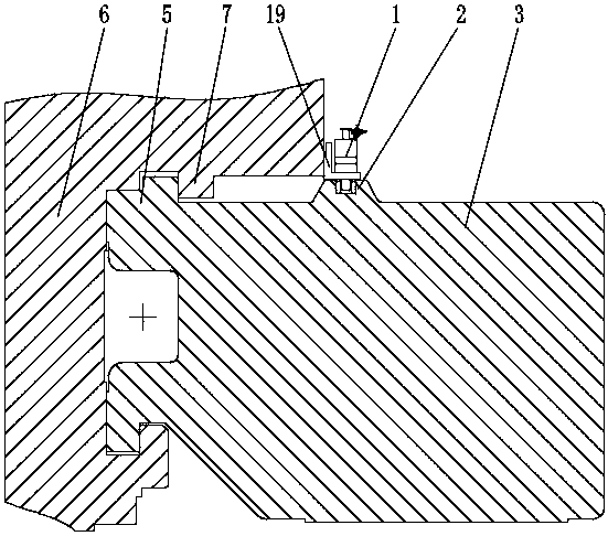
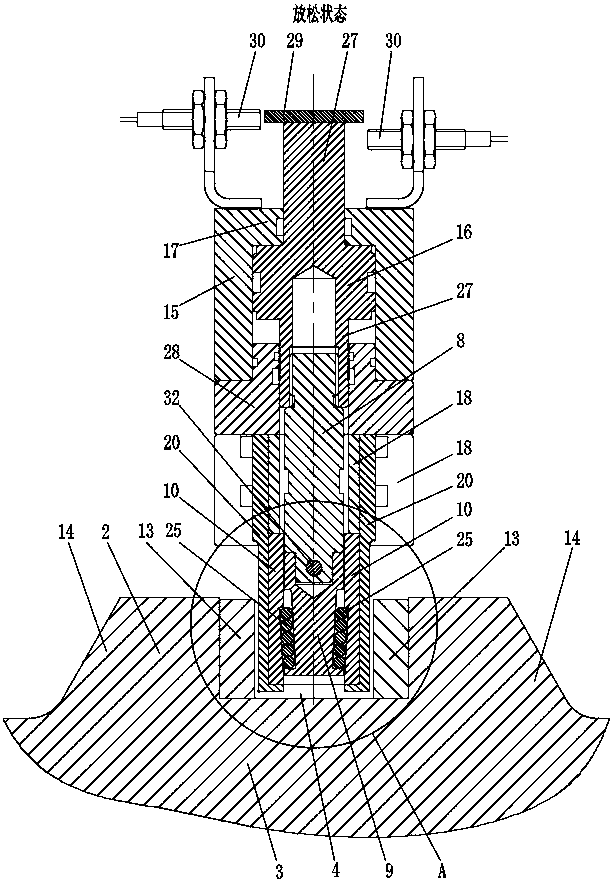
[0032] Such as Figures 1 to 6 As shown, a beam clamping mechanism for a heavy-duty beam lifting gantry machine tool includes a clamping part 1 and a clamping guide rail part 2, the clamping guide rail part 2 is fixedly arranged on a machine column 3, and the clamping guide rail part 2 has a clamping Tighten the guide rail groove 4, the clamping guide rail groove 4 is parallel to the machine tool column guide rail 5, specifically, both sides of the clamping guide rail groove 4 are parallel to the machine tool column guide rail 5, and the clamping part 1 is fixedly connected to the machine tool beam 6;

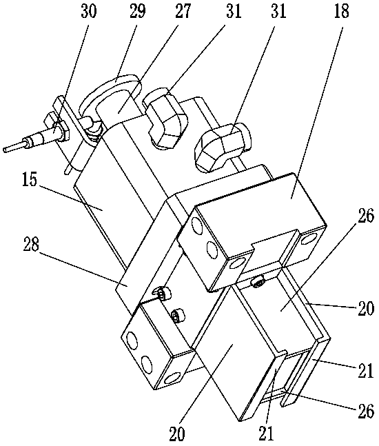
[0033] The clamping part 1 includes a driving structure, the driving structure is connected with a driving rod 8, and can control the driving rod 8 to move axially, the front end of the driving rod 8 is connected with a wedge-shaped pressing block 9, and the rear end of the wedge-shaped pressing block 9 has a mounting hole , the front end of the driving rod 8 is inserted into t...

Embodiment 2

[0041] On the basis of Embodiment 1, the clamping guide rail part 2 is detachably fixed on the machine tool column 3, so that when the clamping guide rail part 2 is worn or damaged due to long-term use, the clamping can be further conveniently and quickly realized. Replacement or removal of the tight guide rail part 2 for maintenance.

Embodiment 3

[0043] Such as figure 1 , 3 , 4, 5, and 6, on the basis of Embodiment 1, the clamping rail part 2 and the machine column 3 are specifically integrally formed, and the left and right sides of the clamping rail part 2 have diagonal braces 14, and the diagonal braces 14 extends along with the length of the clamping guide rail groove 4, which is more conducive to ensuring the connection strength between the clamping guide rail part 2 and the machine column 3, and the diagonal brace part 14 improves the support strength of the machine tool column 3 to the clamping guide rail part 2 .


PUM


Abstract

The invention relates to the technical field of gantry machine tools and discloses a crossbeam clamping mechanism used for a heavy-duty crossbeam-elevating gantry machine tool. The crossbeam clampingmechanism comprises a clamping guide rail part fixedly arranged on a machine tool column, a clamping guide rail groove parallel to a column guide rail and a clamping part fixedly connected with a machine tool crossbeam. The clamping part comprises a driving structure, a driving rod, a wedge-shaped pressing block and wedge-shaped pressing boards. Two sides of the wedge-shaped pressing block are equipped with pressing block slopes. The wedge-shaped pressing boards have pressing board slopes. The pressing block slopes and the pressing board slopes gradually tilt from the back to the front towardsthe axial direction of the driving rod. When the driving rod moves forwards, the wedge-shaped pressing block at the front end is pushed to move forward. The pressing block slopes correspond to and push against the pressing board slopes. The wedge-shaped pressing boards on two sides expand towards the left-right direction and push and clamp tightly against two side surfaces of the guide rail groove. Therefore, the clamping mechanism does not directly contact a crossbeam guide rail and the column guide rail. Damage and deformation to the crossbeam guide rail and the column guide rail due to long-term frequent clamping operation are avoided. Therefore, clamping positioning precision of subsequent crossbeams on the column is ensured.

Description

technical field [0001] The invention relates to the technical field of gantry machine tools, in particular to a beam clamping mechanism for a heavy-duty beam lifting gantry machine tool. Background technique [0002] Heavy-duty gantry machine tools have a wide range of applications, strong processing capabilities, and a high degree of automation. They are general-purpose equipment necessary for modern large-scale and heavy-duty parts processing. In order to adapt to large-sized parts, the size and weight of heavy-duty gantry machine tools are huge, especially the vertically lifting beam and its attached parts can exceed 10 meters in length and weigh more than 50 tons. It is necessary to fix such a long and heavy beam in the vertical direction. , it will cause excessive deformation of the beam and column due to too much clamping force required, which is not conducive to ensuring that the beam under processing has good rigidity, stability and vibration resistance. Therefore, i...

Claims


Application Information

Patent Timeline
Patent Type & Authority Applications(China)
IPC IPC(8): B23Q1/26B23Q1/01B23Q17/00
CPCB23Q1/26B23Q1/012B23Q17/00
Inventor 胥云李志荣李琦陶跃珍颜韵琪黄兵李冰兴
Owner SICHUAN UNIVERSITY OF SCIENCE AND ENGINEERING
Why Eureka
Eureka Blog
Learn More