Plate fixing device hydraulically driven to lift plate and used for welding

A fixing device and hydraulic lifting technology, which is applied in the field of welding plate fixing devices, can solve the problems of difficult and fast execution of the loosening and transporting process, difficult positioning and locking effect, etc.

Inactive Publication Date: 2015-12-02
孙旭东
View PDF10 Cites 2 Cited by
  • Summary
  • Abstract
  • Description
  • Claims
  • Application Information

AI Technical Summary

Problems solved by technology

[0003] However, in some existing fixing devices, it is often difficult to achieve both fast card installation and high-precision positioning an

Method used


Image

  • Plate fixing device hydraulically driven to lift plate and used for welding
  • Plate fixing device hydraulically driven to lift plate and used for welding
  • Plate fixing device hydraulically driven to lift plate and used for welding

Examples


Embodiment Construction

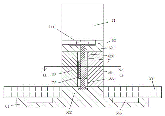
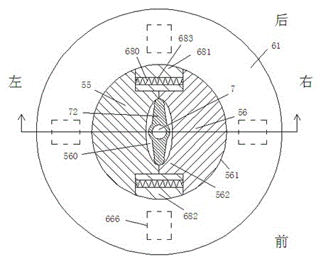
[0010] Combine below Figure 1-3 The present invention will be described in detail.

[0011] According to an embodiment, a hydraulically driven lifting plate welding plate fixing device includes a carrying chassis 61 for carrying the plates 29 to be welded, and is fixedly connected with the carrying chassis 61 and extends in the vertical direction The fixed cylindrical part 62, the fixed cylindrical part 62 includes two fixed columns 681, 682 extending in the vertical direction and facing each other in the diametrical direction, and a top wall part fixedly connected with the upper ends of the two fixed columns 681, 682 621 and the base part 622 fixedly connected with the lower ends of the two fixed columns 681, 682, the telescopic channel 620 extending in the horizontal direction between the two fixed columns 681, 682 is slidably provided with the Two locking sliders 55, 56 symmetrical to the central axis of the solid cylindrical part 62, the two locking sliders 55, 56 all ha...


PUM


Abstract

A plate fixing device hydraulically driven to lift a plate and used for welding comprises a bearing base plate (61) used for bearing a welded plate (29) and a fixing column component (62) which is fixedly connected with the bearing base plate (61) and extends in the vertical direction, wherein the fixing column component (62) comprises two fixing columns (681 and 682) which are opposite to each other in the diameter direction and extend in the vertical direction, a top wall part (62) fixedly connected with the upper ends of the two fixing columns (681 and 682) as well as a column root part (622) fixedly connected with the lower ends of the two fixing columns (681 and 682); two locking sliding blocks (55 and 56) which are symmetric about the center axis of the fixing column component (62) are glidingly arranged in a telescopic channel (620) extending in the horizontal direction between the two fixing columns (681 and 682).

Description

technical field [0001] The invention relates to the field of welding, in particular to a plate fixing device for welding that is hydraulically driven to lift the plate. Background technique [0002] Welding technology is widely used in various fields of industrial production. In some cases, welded workpiece panels need to arrive quickly and be quickly loaded to improve machining productivity. For this kind of fast clamping welding production, high-precision positioning and locking effects are also required, and it needs to be released quickly after welding to facilitate the rapid removal of the workpiece and enter the next production station. [0003] However, in some existing fixing devices, it is often difficult to realize fast clamping and high-precision positioning and locking effects at the same time. And it is also often difficult to perform quickly in the loosening and transporting operation after the processing is completed. Contents of the invention [0004] Th...

Claims


Application Information

Patent Timeline
IPC IPC(8): B23K37/04
CPCB23K37/0408
Inventor 孙旭东
Owner 孙旭东
Why Eureka
Try Eureka