
An unmanned powered parafoil with adjustable installation angle

A technology of powered parafoil and installation angle, which is applied in the field of powered parafoil, can solve the problems of increasing the difficulty of taking off of powered parafoil, reducing the flexibility of powered parafoil, and the inability to adjust the installation angle, etc., to achieve excellent take-off and landing performance, take-off and landing Easy, Increased Flexibility Effects

Active Publication Date: 2018-06-12
AEROSPACE LIFE SUPPORT IND LTD
View PDF7 Cites 0 Cited by
  • Summary
  • Abstract
  • Description
  • Claims
  • Application Information

AI Technical Summary

Problems solved by technology

[0002] At present, the installation angle of the powered parafoil is determined after the parachute is produced and is no longer adjusted. Since the take-off speed of the powered parafoil is higher than the level flight speed in the air, the parachute with high flying speed requirements in the air also has higher ground take-off speed requirements. This increases the take-off difficulty of the powered parafoil, and the greater the risk during take-off; in addition, since the installation angle cannot be adjusted, if the trailing edge of the parafoil is fully released, if the When the engine power increases the flight speed, the powered parafoil will climb. If the engine power is reduced, the powered parafoil will descend, which greatly reduces the flexibility of the powered parafoil to perform tasks.

Method used


Image

  • An unmanned powered parafoil with adjustable installation angle
  • An unmanned powered parafoil with adjustable installation angle
  • An unmanned powered parafoil with adjustable installation angle

Examples


Embodiment Construction

[0019] The present invention will be described in detail below in conjunction with the accompanying drawings and embodiments.

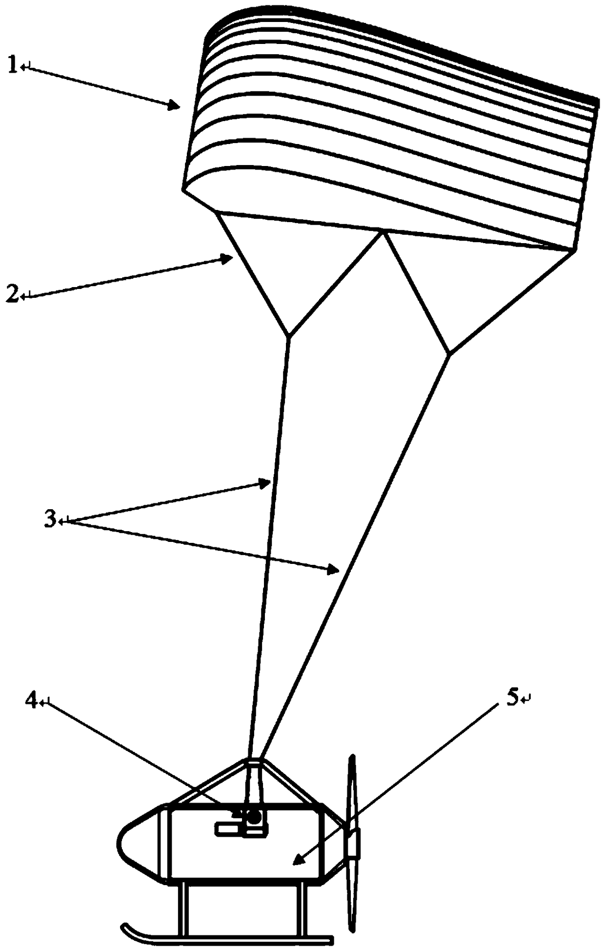
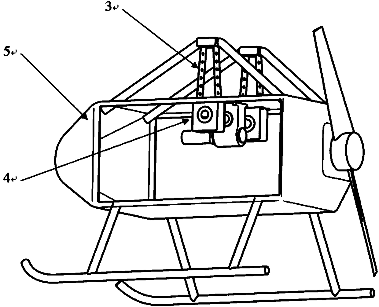
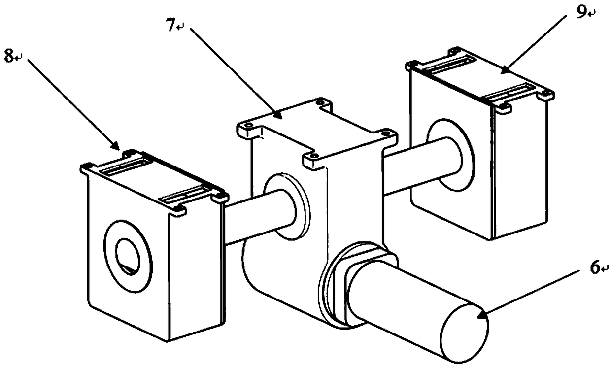
[0020] refer to Figure 1 ~ Figure 2 As shown, the unmanned powered parafoil with adjustable installation angle of the present invention includes an electric retracting mechanism 4, a pod 5, and a canopy 1, and the pod 5 is provided with an electric retracting mechanism 4, and the canopy 1 is provided with a plurality of umbrella ropes 2, which are connected with the electric retracting mechanism 4 through the umbrella ropes 2; the electric retracting mechanism 4 includes a motor 6, a transmission mechanism 7, a left reel 8, and a right reel 9. Described motor 6 is connected with the input end of transmission mechanism 7, and transmission mechanism 7 is provided with two-way output shaft, and two ends of two-way output shaft are provided with the reel shaft 11 that is provided with in the left reel 8, and the reel shaft 11 that is provided with in the...


PUM


Abstract

The invention discloses an unmanned power parafoil with an adjustable mounting angle. The unmanned power parafoil comprises an electric winding mechanism, a suspension compartment and a parachute canopy, wherein the electric winding mechanism is arranged in the suspension compartment; a plurality of parachute ropes are arranged on the parachute canopy, and the parachute canopy is connected with the electric winding mechanism through the parachute ropes; the electric winding mechanism comprises a motor, a transmission mechanism, a left winding drum and a right winding drum; the motor is connected with an input end of the transmission mechanism; the transmission mechanism is provided with a two-way output shaft; two ends of the two-way output shaft are respectively connected with a winding-drum shaft arranged in the left winding drum, and a winding-drum shaft arranged in the right winding drum; an operation band is uniformly wound on each of the winding drums; the parachute bands are divided into four strands; two strands of parachute ropes are respectively connected with two ends of the operation band in the left winding drum, and the other two strands of parachute ropes are respectively connected with two ends of the operation band in the right winding drum. During flight, a mounting angle is adjusted in real time, so that the power parafoil can easily take off or land; the flying speed and the flying height of the power parafoil can be flexibly controlled when the power parafoil flies in air.

Description

technical field [0001] The invention relates to the technical field of a powered parafoil, in particular to an unmanned powered parafoil with an adjustable installation angle. Background technique [0002] At present, the installation angle of the powered parafoil is determined after the parachute is produced and is no longer adjusted. Since the take-off speed of the powered parafoil is higher than the level flight speed in the air, the parachute with high flying speed requirements in the air also has higher ground take-off speed requirements. This increases the take-off difficulty of the powered parafoil, and the greater the risk during take-off; in addition, since the installation angle cannot be adjusted, if the trailing edge of the parafoil is fully released, if the Engine power increases flight speed, and power parafoil will be climbed, if engine power is reduced, power parafoil will descend, and the flexibility of power parafoil execution task is greatly reduced. Con...

Claims


Application Information

Patent Timeline
Patent Type & Authority Patents(China)
IPC IPC(8): B64C31/036
Inventor 李琦周清艳田入东
Owner AEROSPACE LIFE SUPPORT IND LTD
Learn More