Wire-changing structure

A wire-changing structure and connecting wire technology, which is applied to semiconductor/solid-state device components, instruments, semiconductor devices, etc., can solve problems such as damage to the wire-changing structure and electrostatic damage to the wire-changing structure, and achieve the effect of reducing damage

Active Publication Date: 2015-12-02
SHANGHAI AVIC OPTOELECTRONICS +1
View PDF5 Cites 1 Cited by
  • Summary
  • Abstract
  • Description
  • Claims
  • Application Information

AI Technical Summary

Problems solved by technology

like Figure 1C As shown, at the overlapping positions of the film layers of the first metal layer 110 and the second metal layer 130, that is, at the position where the orthographic projection of the second connection line 132 overlaps with the edge of the first body portion 111 ( Figure 1C There are a lot of hexagonal positions in the middle mark), it is easy to accumulate and release static electricity, which will cause static electricity damage to the wire-changing structure and damage the wire-changing structure

Method used


Image

  • Wire-changing structure
  • Wire-changing structure
  • Wire-changing structure

Examples


Embodiment Construction

[0020] The present application will be further described in detail below with reference to the accompanying drawings and embodiments. It should be understood that the specific embodiments described herein are only used to explain the related invention, but not to limit the invention. It should be noted that, for the convenience of description, only the parts related to the related invention are shown in the drawings.

[0021] In addition, it should be noted that the embodiments of the present application and the features of the embodiments may be combined with each other if there is no conflict. The present application will be described in detail below with reference to the accompanying drawings and in conjunction with the embodiments.

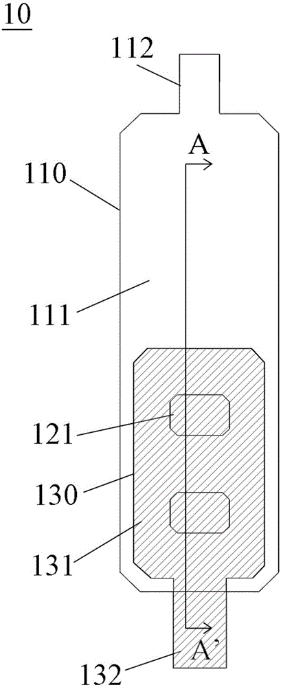
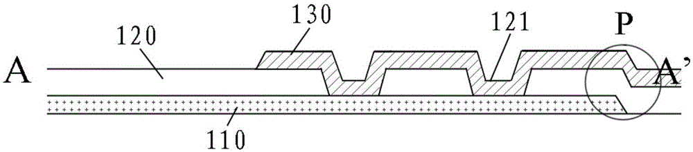
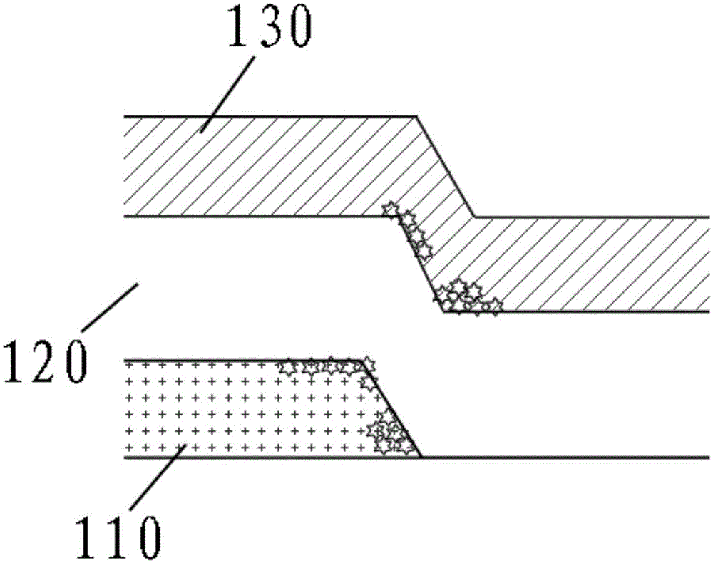
[0022] figure 2 It is a schematic diagram of a wire changing structure 20 provided by an embodiment of the present invention. Similar to the wire changing structure 10 in FIG. 1 , the wire changing structure 20 includes: a first metal laye...


PUM


Abstract

The application provides a wire-changing structure used for electric connection. The wire-changing structure comprises a first metal layer, an insulating layer, and a second metal layer, the first metal layer comprises a first body portion and a first connecting line connected with the first body portion, the insulating layer is arranged on the first metal layer, the second metal layer is arranged on the insulating layer and is electrically connected with the first metal layer, the second metal layer comprises a second body portion and a second connecting line connected with the second body portion, the second metal layer also comprises a redundant portion, one end of the redundant portion is connected with the second body portion, the other end of the redundant portion is connected with the second connecting line, and the redundant portion is configured to easily generate electrostatic discharge relative to the second connecting line. According to the wire-changing structure, the damage caused by electrostatic discharge can be prevented or reduced.

Description

technical field [0001] The present application relates to a wire change structure, and more particularly, to a wire change structure capable of preventing or reducing damage due to electrostatic discharge. Background technique [0002] The wire change structure is widely used in fields such as display panels, for electrically connecting different devices. Figure 1A A conventional wire changer structure 10 is schematically shown, Figure 1B shows along Figure 1A Sectional view taken at A-A'. combine Figure 1A and Figure 1B It can be seen that the wire switching structure 10 includes: a first metal layer 110 , an insulating layer 120 disposed on the first metal layer 110 , and a second metal layer 130 disposed on the insulating layer 120 . The second metal layer 130 may be electrically connected to the first metal layer 110 through, for example, through holes 121 provided in the insulating layer 120 . The first metal layer 110 includes a first body portion 111 and a fir...

Claims


Application Information

Patent Timeline
Patent Type & Authority Applications(China)
IPC IPC(8): H01L23/522H01L23/60H01L21/768G09G3/20
Inventor 席克瑞曹起邵丽琴陈江川
Owner SHANGHAI AVIC OPTOELECTRONICS
Why Eureka
Try Eureka