Bionic trapper

A trap and hinge technology, which is applied to the device, application, animal husbandry and other directions of catching or killing insects, can solve the problems of high cost, limited angle of mosquito trapping, small trapping angle, etc., and achieves low cost and overall structure. Portable and simple effect

Inactive Publication Date: 2015-12-09
SHANGHAI DIANJI UNIV
View PDF7 Cites 3 Cited by
  • Summary
  • Abstract
  • Description
  • Claims
  • Application Information

AI Technical Summary

Problems solved by technology

[0005] 3. Traditional insect traps: the trapping angle of traditional insect traps is not large, and the upper and lower directions are completely closed. Insects that fly to the trap from the upper and lower directions generally cannot be trapped, and the area of ​​the baffle plate only accounts for the surface area of ​​the trap. The cost of traditional traps is relatively high (80 yuan / set), and the actual setting density is far below the design requirements of 9-16 sets / ha
However, there are still a series of problems in the photocatalyst mosquito traps currently on the market: the angle of mosquito trapping is limited, there are certain safety hazards, and the cost is relatively high (300 yuan per unit), which cannot be accepted by the majority of urban residents.

Method used


Image

  • Bionic trapper
  • Bionic trapper

Examples


Embodiment Construction

[0021] In order to make the object, technical solution and advantages of the present invention clearer, various embodiments of the present invention will be described in detail below in conjunction with the accompanying drawings. However, those of ordinary skill in the art can understand that, in each implementation manner of the present invention, many technical details are provided for readers to better understand the present application. However, even without these technical details and various changes and modifications based on the following implementation modes, the technical solution claimed in each claim of the present application can be realized.

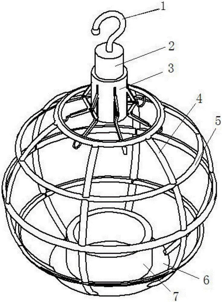
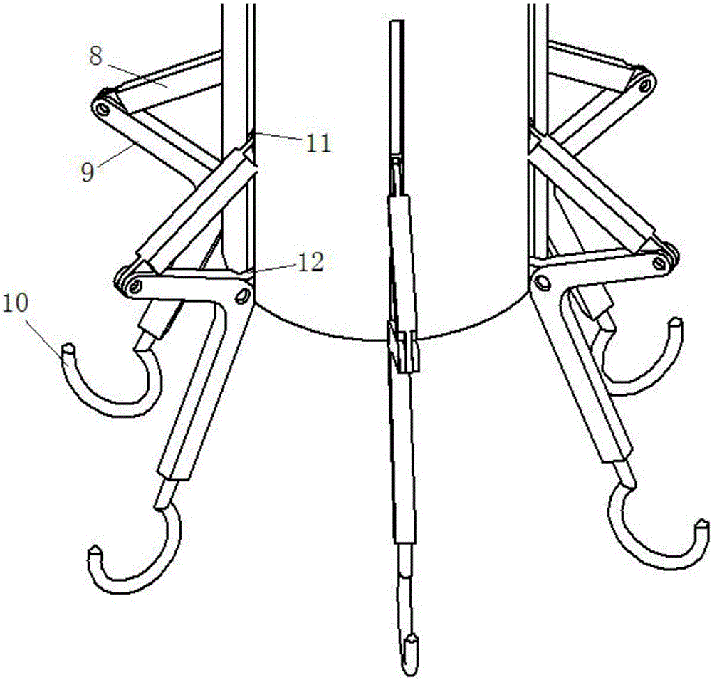
[0022] In order to solve the above-mentioned technical problems, the present invention provides a bionic trap, which combines figure 1 with figure 2 As shown, this embodiment is described in detail.

[0023] As shown in the figure, the technical solution adopted by the present invention is: a novel bionic trap includes an...


PUM


Abstract

The invention discloses a bionic trapper comprising an upper part structure and a lower part structure. The upper part structure has a first hook, a telescopic cylinder, an external cylinder, a plurality of connection parts and a plurality of second hooks, wherein the bottom of the first hook and the top of the telescopic cylinder are fixed; the telescopic cylinder is embedded into the external cylinder; and the plurality of second hooks are connected to the external cylinder via the plurality of connection parts. The lower part structure comprises a plurality of warp loops and a plurality of weft loops intersected with the plurality of warp loops, wherein the warp loops and the weft loop form an external frame of the lower part structure; a chassis is mounted on the bottom of the lower part structure; an accommodating disc is mounted on the chassis; and the external frame is covered with a bionic spider web. The bionic trapper is simply structured and easy to carry, requires low cost and is suitable for large scale promotion and application; and collected insects can be easily recovered.

Description

technical field [0001] The invention relates to the field of agricultural and forestry traps, in particular to a novel bionic trap based on spider web bionics and using adhesives for trapping. Background technique [0002] The existing traps in my country are mainly divided into the following types: [0003] 1. Flat trap: This method is passive, and the trapping angle and orientation are greatly limited, such as sticky fly board, mouse trap, etc. [0004] 2. Black light trap: This trap is not specific, and the cost is high, and the switching time of the light needs to be strictly controlled; the management and maintenance of the black light need to prevent the circuit from being repaired, the lamp tube from being damaged, and the poison from the insect box from leaking. and so on, so as not to cause electric shock, poisoning and other accidents to humans and animals. [0005] 3. Traditional insect traps: the trapping angle of traditional insect traps is not large, and the ...

Claims


Application Information

Patent Timeline
Patent Type & Authority Applications(China)
IPC IPC(8): A01M1/02A01M1/14
Inventor 秦大朋费秋仙王顺利
Owner SHANGHAI DIANJI UNIV
Why Eureka
Try Eureka