Eureka AIR delivers breakthrough ideas for toughest innovation challenges, trusted by R&D personnel around the world.

Small sliding block type low-speed clutch

A clutch and slider-type technology, applied in the field of clutches, can solve problems such as unsuitable installation, impossibility, and failure of clutches to meet application requirements, and achieve the effect of simple principle and structure, and solving the problems of engagement and disengagement

Inactive Publication Date: 2015-12-16
CHINA UNIV OF MINING & TECH
View PDF4 Cites 0 Cited by
  • Summary
  • Abstract
  • Description
  • Claims
  • Application Information

AI Technical Summary

Problems solved by technology

[0003] For some machinery used in special occasions, conventional clutches cannot meet the application requirements
For example, for rescue robots or unmanned mobile equipment with explosive gas environments in coal mines, chemical plants, etc., conventional clutches have three disadvantages: First, such equipment is small in size, while conventional clutches Compared with this type of equipment, it is relatively large (such as a hydraulic coupling), and it is not suitable to be installed on this type of equipment
Second, such equipment is usually operated by remote control, which cannot be realized for clutches that require manual clutching (such as friction clutches)
Third, if a separate actuator is added for the clutch action of the clutch, or an electromagnetic clutch is directly used, for equipment used in explosive gas environments, an additional explosion-proof structure is required, which will greatly increase the design cost. Complexity

Method used


Image

  • Small sliding block type low-speed clutch
  • Small sliding block type low-speed clutch
  • Small sliding block type low-speed clutch

Examples


Embodiment Construction

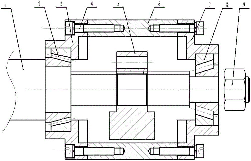
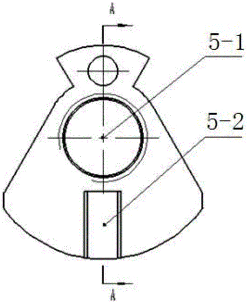
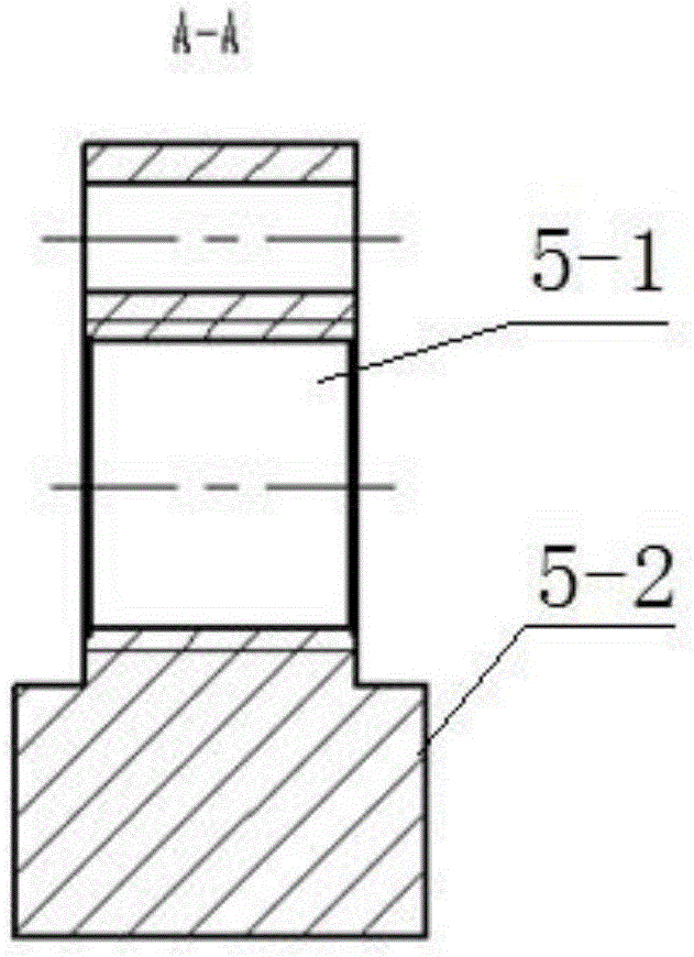
[0018] The present invention will be further explained below in conjunction with the accompanying drawings.

[0019] like Figure 1-7 As shown, the small slider type low-speed clutch of the present invention includes a clutch driving part and a clutch driven part. The active part of the clutch includes a power input shaft 1 and a slider 5, the middle part of the slider 5 is provided with a through hole 5-1, the central axis of the through hole 5-1 deviates from the geometric center of the slider 5, the power input shaft 1 and the through hole 5 -1 is connected by threads, and the outer edge of the slider 5 is provided with a boss 5-2. The clutch driven part includes a left end cover 3, a right end cover 7 and a connecting sleeve 6. The connecting sleeve 6 is sleeved on the power input shaft 1, and the left end cover 3 is fixed on one end of the connecting sleeve 6 by a hexagon socket head cap screw 4 and passed through the left conical roller. The sub-bearing 2 is connected ...


PUM


Abstract

The invention discloses a small sliding block type low-speed clutch which comprises a sliding block. A through hole is formed in the middle of the sliding block. The central axis of the through hole deviates from the geometric center of the sliding block. A power input shaft is in threaded connection with the through hole. A boss is arranged on the outer edge of the sliding block. The power input shaft is sleeved with a connecting sleeve. A left end cover is fixed to one end of the connecting sleeve and connected with the power input shaft through a left conical roller bearing. A right end cover is fixed to the other end of the connecting sleeve and connected with the power input shaft through a right conical roller bearing. The sides, close to the sliding block, of the left end cover and the right end cover are provided with grooves capable of being meshed with the boss. The end faces of the left end cover and the right end cover are each provided with installation holes and threaded holes. According to the small sliding block type low-speed clutch, clutching of the clutch can be achieved only through self-rotation of the power input shaft with no need of external force, the principle and the structure are simple, and the problem of power connection and disconnection of small mobile equipment under the special environment is solved.

Description

technical field [0001] The invention relates to a clutch, in particular to a small slider type low-speed clutch. Background technique [0002] A clutch is like a switch, its main function is to engage or disengage power transmission. The active part and the driven part of the clutch mechanism can be temporarily separated and gradually engaged. The active part and the driven part of the clutch rely on the friction between the contact surfaces, or use liquid as the transmission medium (hydraulic coupling), or Use magnetic transmission (electromagnetic clutch) to transmit torque, so that the two can be temporarily separated and gradually engaged. But above-mentioned clutch all needs to make clutch action by external force, as manpower (pedal), electromagnetic force etc. [0003] For some machinery used in special occasions, conventional clutches cannot meet the application requirements. For example, for rescue robots or unmanned mobile equipment with explosive gas environmen...

Claims


Application Information

Patent Timeline
IPC IPC(8): F16D43/16
Inventor 朱华李雨潭葛世荣
Owner CHINA UNIV OF MINING & TECH
Why Eureka
Eureka Blog
Learn More