Inserting and pulling device

A technology of plug-in device and plug-in hole, which is applied in the field of plug-in device for TR components, which can solve the problems that it is difficult to ensure the safe extraction of TR components and cannot meet the application requirements of TR components.

Active Publication Date: 2015-12-23
BEIJING INST OF RADIO MEASUREMENT
View PDF7 Cites 3 Cited by
  • Summary
  • Abstract
  • Description
  • Claims
  • Application Information

AI Technical Summary

Problems solved by technology

[0003] At present, most of the TR plugging devices actually used are special handles, which cannot meet the application of TR components of different models and sizes.
Especially for the disassembly of TR components when the phased array antenna is repaired, it is difficult to ensure that the TR components can be pulled out safely by ordinary handles.

Method used


Image

  • Inserting and pulling device
  • Inserting and pulling device
  • Inserting and pulling device

Examples


Embodiment 1

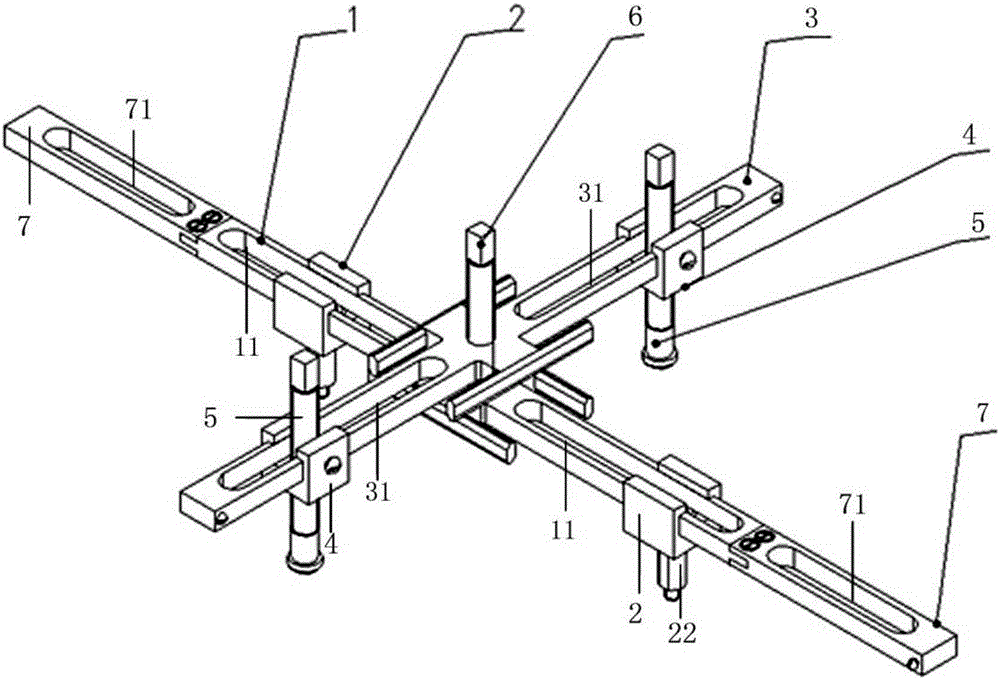
[0046] Such as figure 1 As shown, a plugging device of this embodiment can realize the plugging and unplugging of TR components, including:

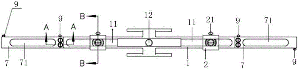
[0047] Plug and unplug rail 1, such as Figure 1-Figure 3 As shown, the plug-in guide rail 1 is elongated, and the plug-in guide rail 1 is provided with a first long hole 11, and the middle part of the plug-in guide rail 1 is provided with a first plug-in hole 12, and there are two first long holes 11. Two first elongated holes 11 are symmetrically arranged on both sides of the first insertion hole 12; both ends of the plug-in guide rail 1 are provided with limit screws 9.

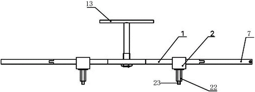
[0048] first slider 2, as in Figure 1-Figure 4 As shown, the first slider 2 is sleeved on the plug-in guide rail 1, and the first fastening screw 21 is inserted on the side wall of the first slider 2, and the first slider 2 can be tightened by tightening the first The fastening screw 21 locks the first slider 2 and the outer wall of the plug-in guide rail 1; the ...

Embodiment 2

[0052] The plug-in device of this embodiment not only includes the plug-in guide rail and the first slider in Embodiment 1, but also includes:

[0053] Support rails 3, such as figure 1 , Figure 5 with Image 6 As shown, the middle part of the support rail 3 is provided with a second insertion hole 32, the support rail 3 is elongated, and the support rail 3 is provided with a second elongated hole 31; the second elongated hole 31 is two, and the two second elongated holes The holes 31 are symmetrically arranged on both sides of the second insertion hole 32 . The two ends of the support guide rail are also provided with limit screws 9 to avoid the sliding of the second slide block.

[0054] The second slider 4, such as Figure 5-Figure 7 As shown, the second slider 4 is sleeved on the support guide rail 3, and a third fastening screw 41 is inserted on the side wall of the second slider 4, and the second slider 4 can be tightened by tightening the third fastening screw. Th...


PUM


Abstract

The invention relates to an inserting and pulling device. The inserting and pulling device comprises an inserting and pulling guide rail and first sliding blocks. The inserting and pulling guide rail is in a long strip shape. First long holes are formed in the inserting and pulling guide rail. A first inserting and pulling hole is formed in the middle of the inserting and pulling guide rail. The inserting and pulling guide rail is sleeved with the first sliding blocks. A first fastening screw is inserted in one side wall of each first sliding block. Each first sliding block can be locked to the outer wall of the inserting and pulling guide rail by tightening the corresponding first fastening screw. A connecting post is fixed to the bottom of each first sliding block. A second fastening screw is inserted in each connecting post. The second fastening screws are inserted into an object to be inserted and pulled and tightened so that the first sliding blocks and the object to be inserted and pulled can be fixed. The inserting and pulling device can meet the inserting and pulling requirements of transmitter and receiver (TR) modules of different sizes due to the arrangement of the inserting and pulling guide rail and the first sliding blocks.

Description

technical field [0001] The invention relates to a plugging device, in particular to a plugging device of a TR assembly. Background technique [0002] In modern radars, phased array antennas are widely used, and in phased array antennas, the array is distributed with a large number of plug-in components, such as TR components, confluence components, power supply components and power divider components, etc., especially in terms of the number of TR components most. When assembling phased array antennas, the TR components are generally installed close to the cold plate, and heat-conducting silicone grease needs to be applied evenly on both sides of the TR components. Design a special plug-in device according to the size of the TR component. [0003] At present, most of the TR plugging devices actually used are special-purpose handles, which cannot meet the application of TR components of different models and sizes. Especially for the disassembly of TR components when repairi...

Claims


Application Information

Patent Timeline
Patent Type & Authority Applications(China)
IPC IPC(8): B25B27/00
CPCB25B27/00
Inventor 熊强王超
Owner BEIJING INST OF RADIO MEASUREMENT
Why Eureka
Try Eureka