Plant power generation system

A power generation system and plant technology, applied in generators/motors, electrical components, single-network parallel feeding arrangements, etc., can solve problems such as high development costs, inability to get rid of complex processes of multiple transformations, and unfavorable large-scale development and utilization. , to achieve the effect of low cost

Inactive Publication Date: 2015-12-23
HOHAI UNIV
View PDF4 Cites 3 Cited by
  • Summary
  • Abstract
  • Description
  • Claims
  • Application Information

AI Technical Summary

Problems solved by technology

However, today’s biomass energy utilization method is generally to convert biomass itself into ethanol, hydrogen and other substances, and use it to generate electricity, which cannot get rid of the complicated process of multiple conversions. It will cause energy loss and certain pollution, which is not conducive to large-scale development and utilization

Method used


Image

  • Plant power generation system
  • Plant power generation system
  • Plant power generation system

Examples


Embodiment Construction

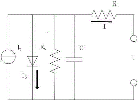
[0016] Plant power generation technology mainly uses the light reaction in plant photosynthesis. When photons hit the pigment molecules, chlorophyll will absorb light of a specific wavelength, excite high-energy electrons, and form a 1.13v potential difference with the outside world. Using this potential difference, a certain amount of current can be output. Power equivalent models such as figure 1 , which is equivalent to a constant current source connected in parallel with a forward diode, where Is is the current flowing through the forward diode, and Rs is the leakage current due to the different internal structure and material of the power generation unit and the contact gap of the device, so that the current that should flow The overload current is the equivalent resistance caused by the short circuit, and C is the junction capacitance. Rn is the equivalent resistance of the series circuit voltage drop.

[0017] It is the current source formed by the light reaction of p...


PUM


Abstract

The invention relates to a plant power generation system, and the system can directly use electric energy generated by photoreaction in a process of plant photosynthesis and stably output electric energy at a state of living plants. The system consists of a power module, a controller module and an inverter module. The power module consists of a plurality of power generation unit arrays, and a plurality of power generation modules are connected in parallel to form a power generation system, thereby enabling the output electric energy to be stable and reliable, and enabling the efficiency to be higher. The living plants are directly used for power generation under the condition of not affecting the growth of plants, so the system is green and environment-friendly, the energy is clean and renewable, and the cost is low.

Description

technical field [0001] The invention relates to a plant power generation system, belonging to the field of biomass power generation systems. Background technique [0002] Energy is the lifeblood of a country's national economy. With the rapid development of my country's economy in recent years, the contradiction between energy and environmental issues has become increasingly prominent. Biomass energy is more and more dominant in the development and utilization of new energy due to its green and non-polluting characteristics. However, today’s biomass energy utilization method generally converts biomass itself into ethanol, hydrogen and other substances, and uses it to generate electricity. It cannot get rid of the complicated process of multiple transformations. Not only the development cost is high, but also the transformation of multiple energy forms is also difficult. It will cause energy loss and certain pollution, which is not conducive to large-scale development and ut...

Claims


Application Information

Patent Timeline
Patent Type & Authority Applications(China)
IPC IPC(8): H02N11/00H02J3/38
Inventor 袁蓓
Owner HOHAI UNIV
Why Eureka
Try Eureka