Flange transfer communication tower

A communication tower and flange technology, applied in the field of communication towers, can solve the problems of material waste, complex operation of anchor bolts, and prolonging the construction period

Active Publication Date: 2017-05-10
HUAXIN CONSULTATING CO LTD
View PDF5 Cites 0 Cited by
  • Summary
  • Abstract
  • Description
  • Claims
  • Application Information

AI Technical Summary

Problems solved by technology

[0004] The purpose of the present invention is to overcome the deficiencies in the prior art, and provide a flange transfer communication tower, which can effectively solve the problem that the embedded anchor bolts and the plane flange at the lower end of the steel member of the tower cannot be connected in the prior art. , it is necessary to reprocess the plane flange at the lower end of the steel member of the tower body or re-embed the anchor bolts. Not only is the operation complicated, it will cause waste of materials, and more importantly, it will prolong the entire construction period.

Method used


Image

  • Flange transfer communication tower
  • Flange transfer communication tower
  • Flange transfer communication tower

Examples


Embodiment 1

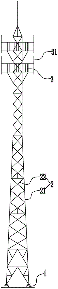
[0033] Embodiment 1: as figure 1 , figure 2 As shown, a flange transfer communication tower includes a base 1 and a tower body 2 arranged on the base. Two maintenance platforms 3 are arranged on the upper part of the tower body, and a plurality of antenna hanging rods 31 for hanging communication antennas are arranged on the outer side of the maintenance platform. The tower body includes three main support towers 21 extending from bottom to top and several connecting towers 22 connecting the two main support towers. The lower end of the main supporting tower rod is connected with the base through the transfer flange structure 4 .

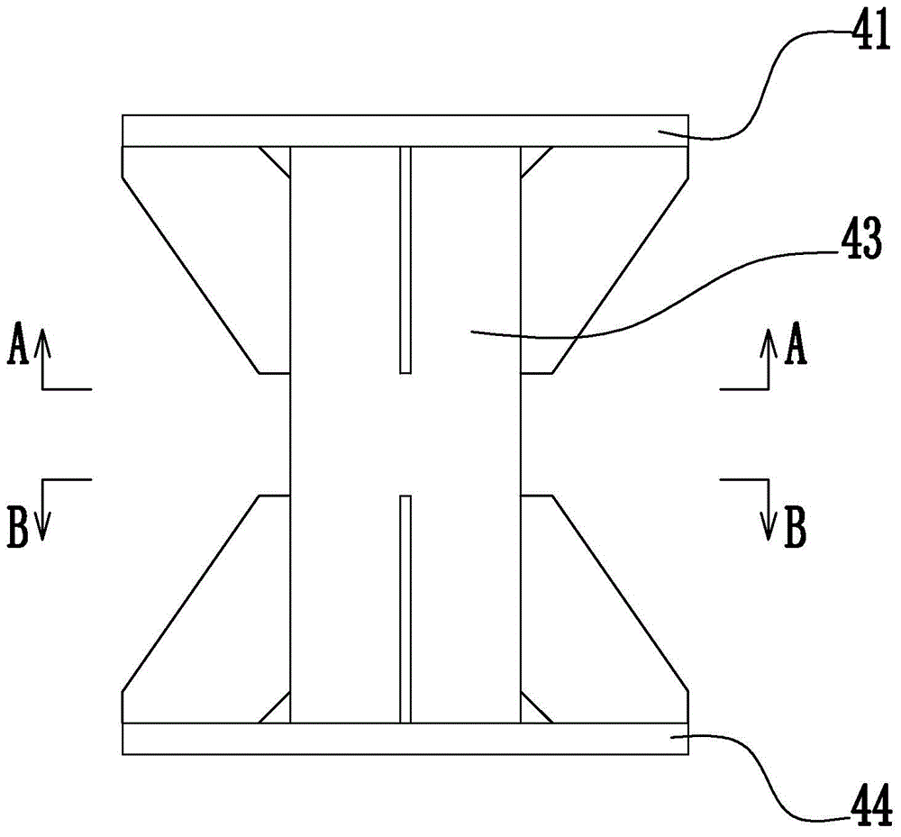
[0034] Such as figure 2 , image 3 , Figure 4 , Figure 5 As shown, the adapter flange structure includes an upper adapter flange 41 , a lower adapter flange 44 and a connecting pipe 43 connecting the upper adapter flange and the lower adapter flange. Several upper reinforcing plates 42 uniformly distributed in the circumferential direction ...

Embodiment 2

[0036] Embodiment 2: the remaining structure of this embodiment is with reference to embodiment 1, and its difference is:

[0037] like Image 6 As shown, a flange transfer communication tower also includes a controller, a trigger rope 6, a connecting rope 8, an installation base 10, and a trigger device 7 and an execution device 9 arranged on the installation base. The triggering device and the actuator are located on the same side of the tower.

[0038] like Image 6 , Figure 7 As shown, the trigger device 7 includes a trigger cylinder 71 vertically arranged on the top surface of the installation base, a trigger piston 73 slidably arranged in the trigger cylinder, and a second trigger cylinder arranged on the side of the trigger cylinder and below the trigger piston. The lower limit block 72 and the pressure sensor 713 arranged in the trigger cylinder and above the trigger piston. The pressure sensor is connected with the controller through the signal line. Trigger the...


PUM


Abstract

The invention discloses a flange transfer communication tower and aims at providing a communication tower capable of effectively solving the problems that operations are complicated, material wastes are caused and the whole construction period is prolonged since a flat flange at the lower end of a tower body steel component needs to be re-processed or a foot bolt needs to be re-embedded when an embedded foot bolt can not be connected with the flat flange at the lower end of the tower body steel component. The flange transfer communication tower comprises a base and a tower body arranged on the base, wherein the tower body comprises at least three main support tower poles extending from bottom to top; the lower ends of the main support tower poles are connected with the base through transfer flange structures; the transfer flange structures comprise upper transfer flange plates, lower transfer flange plates and connecting pipes; the lower ends of the main support tower poles are provided with lower connecting flange plates, and the upper transfer flange plates are connected with the lower connecting flange plates through holes; the upper surface of the base is provided with a plurality of foot bolts connected with the lower transfer flange plates, and the lower transfer flange plates are fixedly connected to the base through the foot bolts.

Description

technical field [0001] The invention relates to a communication tower, in particular to a flange transfer communication tower. Background technique [0002] Bolt connection is widely used as the most common connection method between steel components in communication steel towers; if the steel components cannot be directly connected in the same plane, the connection method of flat flange combined with bolts is used to solve it, such as between pipes and pipes The connections between the angle steel and the anchor bolts, between the lightning rod and the tower body are all connected by plane flanges. [0003] Due to the differences in the properties and stress of the materials to be connected, the size of the flange connections required by each and the number and distribution of the connecting bolts are different. When the difference is large, the traditional method is to envelop the design, which is handled according to the end with a large force and a large number of bolts....

Claims


Application Information

Patent Timeline
Patent Type & Authority Patents(China)
IPC IPC(8): E04H12/08
Inventor 张珩姚云龙竹影章跃军田大年周燕青朱国泉王刚
Owner HUAXIN CONSULTATING CO LTD
Why Eureka
Try Eureka