
Passenger train baggage counter top plate structure

A technology for railway passenger cars and luggage racks, which is applied to the direction of the railway roof, etc., which can solve the problems of increased noise in the car, falling off of the Velcro cover strip, and easy damage to the side roof, so as to avoid loosening, increase the aesthetic effect, and improve the aesthetic effect Effect

Active Publication Date: 2016-01-06
CRRC NANJING PUZHEN CO LTD
View PDF6 Cites 0 Cited by
  • Summary
  • Abstract
  • Description
  • Claims
  • Application Information

AI Technical Summary

Problems solved by technology

[0002] The position of air-conditioning air outlet on the roof of domestic railway luggage counter usually adopts an open structure, which can meet the requirements of air outlet, but the structure of the inner roof can be seen at the air outlet, and the aesthetics needs to be further improved. The cover strip structure is adopted and connected to the top plate by Velcro. Due to the limitation of the Velcro itself, after a period of time, the Velcro will loosen or the cover strip will fall off, which will increase the noise in the car and affect the aesthetic effect of the car. In addition, the side roof forms a chamber with the partition wall and the flat roof, which is used for storing luggage. Since there are no corresponding anti-collision measures, the side roof is easily damaged

Method used


Image

  • Passenger train baggage counter top plate structure
  • Passenger train baggage counter top plate structure
  • Passenger train baggage counter top plate structure

Examples


Embodiment Construction

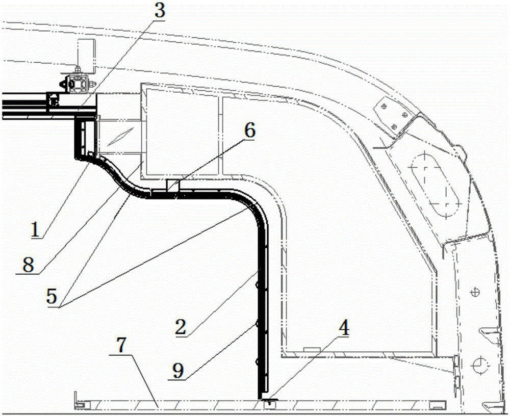
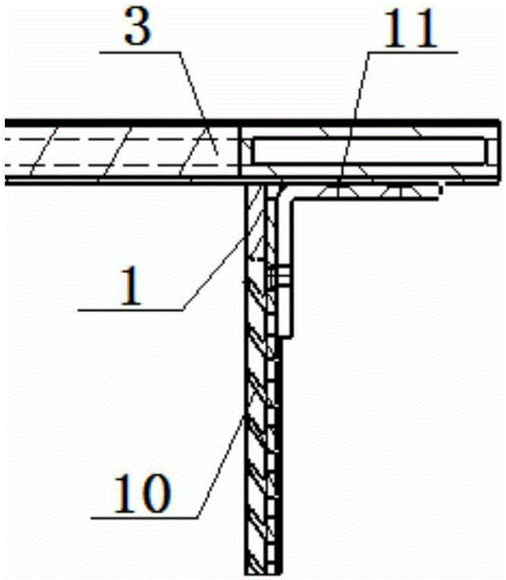
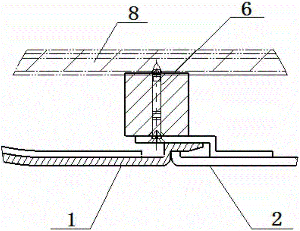
[0019] Such as Figure 1 to Figure 4 As shown, the roof structure of the railway passenger car luggage platform in this embodiment includes a flat roof plate 3, a side roof plate 2, a curved plate 1 that passes through a platform flat roof plate 7, and is fixed to the air outlet grille 10 and is fixed on the vehicle partition wall 14. Aluminum bead 5. The upper end of the side top plate 2 is hoisted below the air-conditioning duct 8 through the wooden lining 6, and the lower end is fixed on the platform top plate 7 through the connecting angle iron 4. The curved plate 1 is provided with a rectangular hole matching the peripheral size of the air outlet grille 10, and the air outlet grille 10 is embedded in the rectangular hole, and fixed with the curved plate 1 by glue to make the outer surface smooth. Such as figure 2 As shown, the upper end of the curved plate 1 is fixed below the flat roof panel 3 by connecting iron 11 . Such as image 3 As shown, the lower end of the c...


PUM


Abstract

The invention relates to a passenger train baggage counter top plate structure. The passenger train baggage counter top plate structure comprises a train roof flat top plate, a side top plate, a passing platform flat top plate, a bent plate and rigid pressing strips, wherein the bent plate and an air outlet grid are fixed together, and the rigid pressing strips are fixed to a train partition wall. The upper end of the bent plate is fixed to the train roof flat top plate, and the lower end of the bent plate is fixedly inserted into the upper end of the side top plate. The shape of the rigid pressing strips is matched with that of a spliced body of the side top plate and the bent plate, and the bent plate and the side top plate are pressed on the rigid pressing strips through rubber strips. A closed structure is adopted for a train baggage counter top plate, so that the air outlet requirement is met, and the attractive effect is improved; for facilitating overhaul of air conditioning equipment, a detachable structure is adopted for the part; a certain number of anti-collision strips are installed on the side top plate in a full-length mode, so that the side top plate is protected, and the attractive effect is improved; in addition, a lap joint mode is adopted for the parts, close to the partition wall, of the two sides of the top plates, so that looseness or disengagement is effectively avoided.

Description

technical field [0001] The invention relates to a top plate structure of a luggage platform of a railway passenger car, and belongs to the technical field of rail vehicle interior structures. Background technique [0002] The position of air-conditioning air outlet on the roof of domestic railway luggage counter usually adopts an open structure, which can meet the requirements of air outlet, but the structure of the inner roof can be seen at the air outlet, and the aesthetics needs to be further improved. The cover strip structure is adopted and connected to the top plate by Velcro. Due to the limitation of the Velcro itself, after a period of time, the Velcro will loosen or the cover strip will fall off, which will increase the noise in the car and affect the aesthetic effect of the car. , In addition, the side roof, the partition wall and the flat roof form a chamber for storing luggage. Since there are no corresponding anti-collision measures, the side roof is easily dama...

Claims


Application Information

Patent Timeline
Patent Type & Authority Applications(China)
IPC IPC(8): B61D17/14
Inventor 周正宇陆丽芬章光明王卫高健飞姜艳林韩文娟林琳张玉萍牟亚杰肖露杨泽东
Owner CRRC NANJING PUZHEN CO LTD
Learn More