
Refrigerant circulation system and heat pump equipment with same

A refrigerant circulation system and heat pump technology, applied in lighting and heating equipment, heat pumps, refrigerators, etc., can solve problems such as compressor liquid shock, and achieve the effect of solving compressor liquid shock

Inactive Publication Date: 2016-01-06
GREE ELECTRIC APPLIANCES INC
View PDF5 Cites 4 Cited by
  • Summary
  • Abstract
  • Description
  • Claims
  • Application Information

AI Technical Summary

Problems solved by technology

[0003] The main purpose of the present invention is to provide a refrigerant circulation system and heat pump equipment with it, so as to solve the problem of easy compressor liquid shock in the prior art

Method used


Image

  • Refrigerant circulation system and heat pump equipment with same

Examples


Embodiment Construction

[0019] It should be noted that the embodiments in the application and the features in the embodiments can be combined with each other if there is no conflict. Hereinafter, the present invention will be described in detail with reference to the drawings and in conjunction with the embodiments.

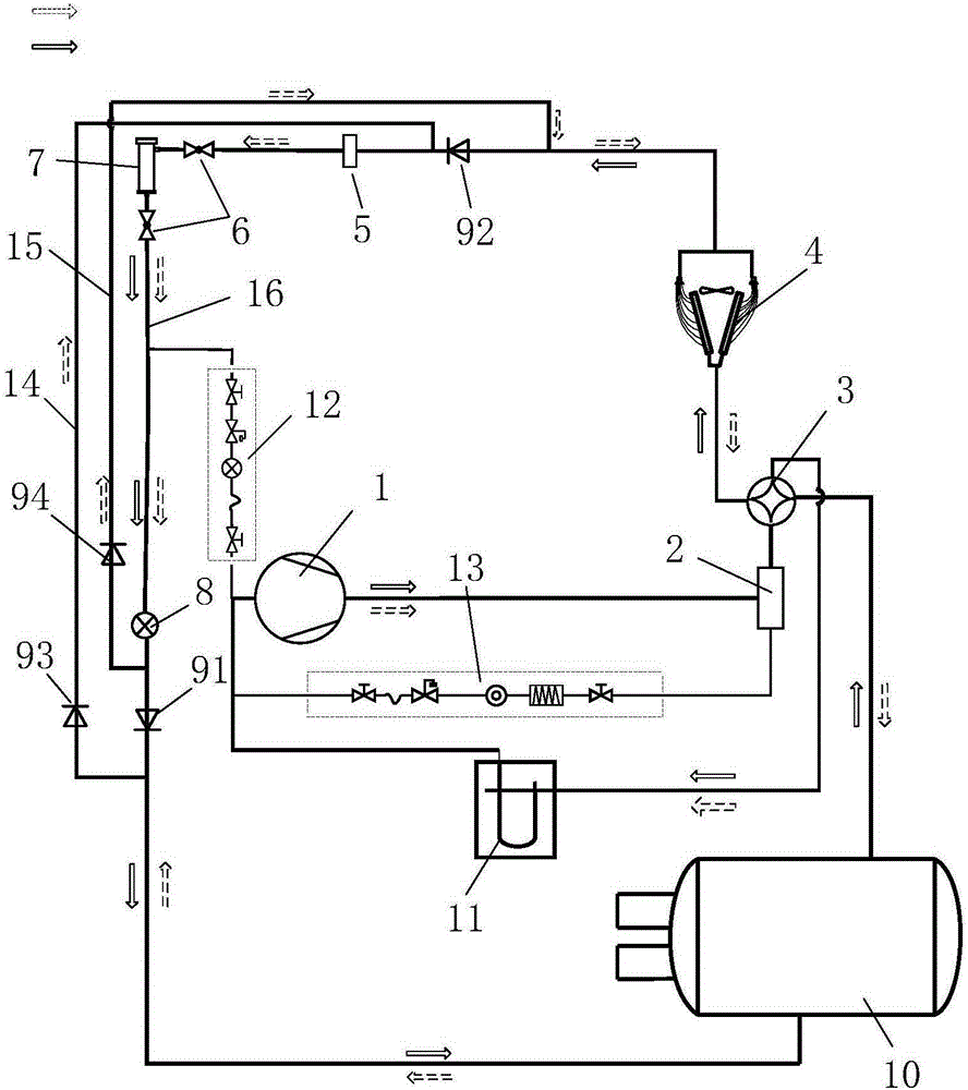
[0020] Such as figure 1 As shown, the refrigerant circulation system of this embodiment includes a compressor 1, a first heat exchanger 10, and a second heat exchanger 4 connected in sequence. The storage volume of the first heat exchanger 10 is larger than that of the second heat exchanger. The storage volume of the heat exchanger 4 is connected with a liquid storage tank 5 on the pipeline 16 connecting the first heat exchanger 10 and the second heat exchanger 4.

[0021] During the operation of the refrigerant circulation system, in order to prevent a large amount of refrigerant from the first heat exchanger 10 with a larger storage volume from flooding into the second heat exchanger 4, t...


PUM


Abstract

The invention provides a refrigerant circulation system and heat pump equipment with the same. The refrigerant circulation system comprises a compressor, a first heat exchanger and a second heat exchanger which are connected in sequence. The storage volume of the first heat exchanger is larger than that of the second heat exchanger, and a liquid storage tank is connected to a pipeline enabling the first heat exchanger and the second heat exchanger to be connected. By means of the technical scheme, in order to prevent a large amount of refrigerating fluid of a refrigerant coming from the first heat exchanger with the larger storage volume from flowing over into the second heat exchanger, the liquid storage tank is arranged between the first heat exchanger and the second heat exchanger to store part of the refrigerating fluid, and thus the problem that liquid impact of the compressor is caused due to the fact that a large amount of refrigerating fluid flows over into the second heat exchanger is solved.

Description

Technical field [0001] The invention relates to a refrigerant circulation system and a heat pump device having the same. Background technique [0002] In the prior art, the heat pump equipment includes a first heat exchanger (such as a flooded shell and tube heat exchanger), a second heat exchanger (such as a fin heat exchanger), a four-way valve and a compressor. Take screw type air-cooled heat pump equipment with flooded shell and tube heat exchanger as an example. When cooling, the refrigerant liquid is mainly accumulated in the flooded shell and tube heat exchanger. When heating, the volume of refrigerant liquid is accumulated on the fins. In heat exchangers and corresponding pipelines, in general, because the storage volume of the full-liquid shell and tube heat exchanger is larger than the storage volume of the fin heat exchanger and the corresponding pipelines, such a situation may occur: When heating, a large amount of refrigerant liquid rushes to the fin heat exchange t...

Claims


Application Information

Patent Timeline
Patent Type & Authority Applications(China)
IPC IPC(8): F25B30/02
Inventor 钟海玲黄凯亮孙雷鸣胡乾龙吉剑林李敏
Owner GREE ELECTRIC APPLIANCES INC
Learn More