Tightrope walking robot structure with double flywheels

A technology of tightrope walking and robot, applied in the field of double flywheel tightrope walking robot structure, can solve the problems of flexible steel wire deformation, increase the difficulty and uncertainty of control, increase the stability of robots and tightrope acrobats, etc., and achieve the effect of reducing control difficulty.

Active Publication Date: 2017-03-22
GUILIN UNIV OF ELECTRONIC TECH
View PDF1 Cites 0 Cited by
  • Summary
  • Abstract
  • Description
  • Claims
  • Application Information

AI Technical Summary

Problems solved by technology

However, this patented robot does not consider the influence of the flexibility of the steel wire on the balance of the robot. The torque generated by the high-speed rotation of the gyro will deform the flexible steel wire, which increases the difficulty and uncertainty of control.
[0004] In the article "The Wonderful Use of Flywheels" written by Jia Shuhui in the first issue of "Mechanics and Practice" in 2002, he proposed that the orientation of objects can be controlled by driving the flywheel to obtain counter torque. This principle can not only control the attitude of the spacecraft, but also can To increase the stability of robots and tightrope acrobats, this article only proposed a possibility of using the flywheel to control the balance, and did not conduct in-depth discussions to propose an effective solution

Method used


Image

  • Tightrope walking robot structure with double flywheels
  • Tightrope walking robot structure with double flywheels

Examples


Embodiment Construction

[0017] The technical solutions of the present invention will be further described below in conjunction with the embodiments shown in the accompanying drawings.

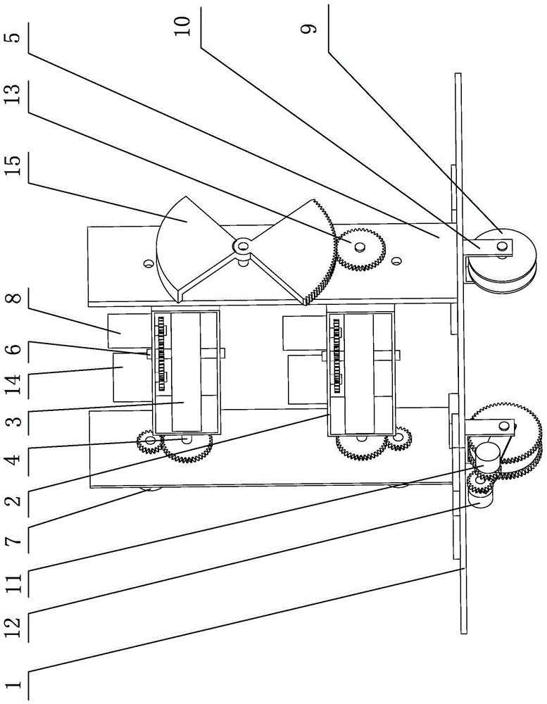
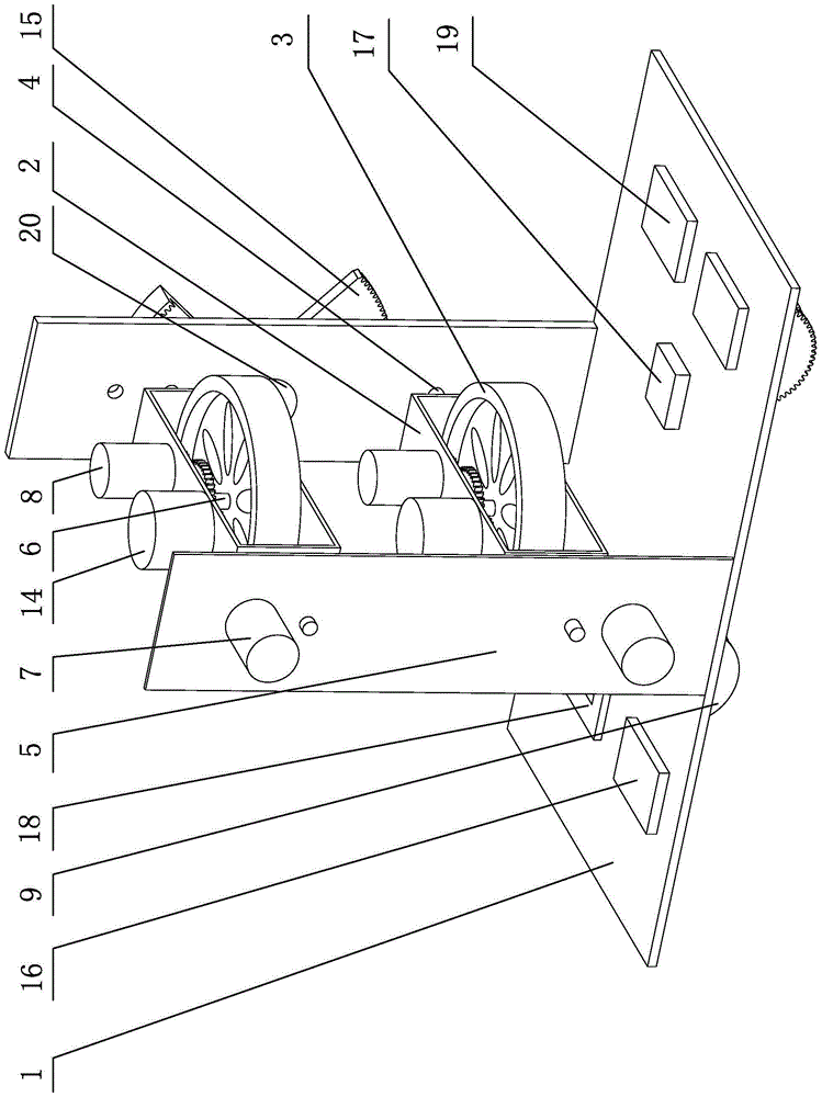
[0018] The technical solution of the double-flywheel tightrope walking robot structure of the present invention includes a balance device, a walking device and a control device based on the base plate 1 .

[0019] The base plate 1 is a flat plate, and a support frame 5 is arranged on the base plate 1, and the support frame 5 is composed of left and right side plates, such as figure 1 , figure 2 shown.

[0020] The balance device includes upper and lower balance frames 2 and upper and lower balance flywheels 3, and the upper and lower balance frames 2 are placed horizontally (the length direction of the balance frame 2 is left and right, and the inner hollow part of the balance frame 2 is the front , rear direction) between the left and right side plates of the support frame 5, each balance frame 2 is installed on t...


PUM


Abstract

The invention discloses a double-flywheel steel-wire-walking robot structure. A balance device of the double-flywheel steel-wire-walking robot structure comprises an upper balance frame, a lower balance frame, an upper balance flywheel and a lower balance flywheel; the upper balance frame and the lower balance frame are installed in a supporting frame on a base plate, and the upper balance flywheel and the lower balance flywheel are horizontally installed in the upper balance frame and the lower balance frame respectively; the supporting frame is provided with balance frame motors for driving the upper balance frame and the lower balance frame to do small-angle synchronization reversing rotation through linkage mechanisms and provided with balance frame encoders for detecting the rotation ranges of the upper balance frame and the lower balance frame respectively, and the balance frames are provided with balance flywheel motors for driving the balance flywheels to rotate at a high speed and balance flywheel encoders for detecting the rotating speed; a walking device of the double-flywheel wire-walking robot structure comprises a front steel wire walking wheel, a back steel wire walking wheel, a walking wheel motor and a walking wheel encoder, wherein the front steel wire walking wheel and the back steel wire walking wheel are installed at the bottom of the base plate, one steel wire walking wheel is driven by the walking wheel motor, and the walking wheel encoder is used for detecting the rotating speed. By means of the double-flywheel wire-walking robot structure, the posture of a machine body during inclination is effectively controlled, and self-balance control of the machine body on a rigid or soft steel wire is achieved.

Description

technical field [0001] The invention relates to a tightrope walking robot structure, in particular to a double flywheel tightrope walking robot structure. Background technique [0002] A tightrope walking robot is a mechanical device that can maintain self-balancing and walk on a flexible steel wire, mainly through the rotation and translation of the balance bar to achieve self-balancing. [0003] Shanghai Jiaotong University applied for the "tightrope walking robot" invention patent (application number 03129064.7). The technical solution of the invention is to utilize the stability of the gyroscope to realize self-balancing by using the gyroscope as a stabilizing device. However, this patented robot does not consider the influence of the flexibility of the steel wire on the balance of the robot. The torque generated by the high-speed rotation of the gyro will deform the flexible steel wire, thereby increasing the difficulty and uncertainty of control. [0004] In the arti...

Claims


Application Information

Patent Timeline
Patent Type & Authority Patents(China)
IPC IPC(8): B25J9/08B25J9/16
CPCB25J9/08B25J9/16
Inventor 黄用华张明明钟艳如庄未李天生何淑通刘成举江汉钟永全
Owner GUILIN UNIV OF ELECTRONIC TECH
Why Eureka
Try Eureka