Cavity Backed Slot Antenna Structure

A slot antenna and slot technology, which is applied in the field of cavity-backed slot antenna structures, can solve the problem of insufficient thickness of the cavity, and achieve the effect of small occupied space and space restrictions, and low height

Active Publication Date: 2018-06-26
SHENZHEN SUNWAY COMM
View PDF7 Cites 0 Cited by
  • Summary
  • Abstract
  • Description
  • Claims
  • Application Information

AI Technical Summary

Problems solved by technology

In addition, some existing technologies use high-dielectric materials to fill the cavity to reduce the size, and the cavity thickness is not thin enough for wireless devices such as tablets or laptops

Method used


Image

  • Cavity Backed Slot Antenna Structure
  • Cavity Backed Slot Antenna Structure
  • Cavity Backed Slot Antenna Structure

Examples


Embodiment 1

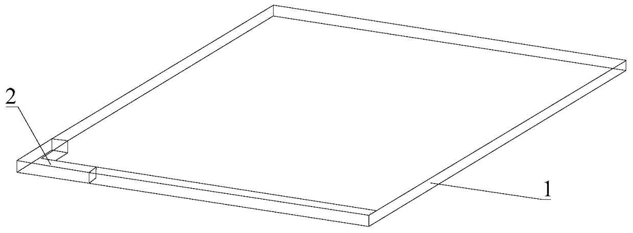
[0030] Please refer to figure 1 , the present invention relates to an electronic device, such as wireless devices such as ultra-thin mobile phones, tablet computers or notebook computers, which includes a frame 1, a full-screen display can be arranged on the upper surface of the frame, the display can be a metallized screen, and the lower surface of the frame Then a metal back shell can be provided. The frame 1 can also be a metal frame, where necessary slots and other positions are non-metallic. figure 1 Each corner of the frame is a right angle, and optionally, it may also have a structure such as rounded corners to meet the needs of different users. A cavity-backed slot antenna structure 2 is arranged inside a corner of the frame 1, and the antenna structure is L-shaped and suitable for placing in a corner.

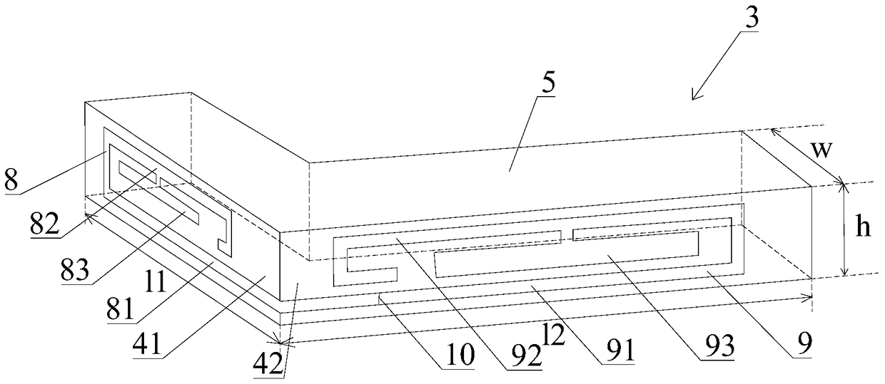
[0031] Please refer to figure 2 It is a schematic diagram of the specific structure of the antenna structure 2, the antenna structure includes a metal cavity 3, th...

Embodiment 2

[0036] Such as Figure 5 As shown, the second embodiment of the present invention adds an insulating material layer 12 on the basis of the first embodiment. The insulating material layer 12 is a PTFE or PC-ABS material layer, and the insulating material layer 12 covers the first outer surface 41 and the second outer surface 42 of the metal cavity; optionally, the insulating material layer 12 The thickness is 0.6-0.9 mm, preferably 0.75 mm. Preferably, the insulating material layer 12 may also cover the upper surface, inner surface or end surface of the metal cavity if the size requirements are met. In this embodiment, the slot structure of the antenna is not visible from the outside, the appearance is simple and beautiful, and at the same time, it can isolate and protect the antenna.

[0037] To sum up, in the structure of the cavity-backed slot antenna provided by the present invention, the metal cavity of the cavity-backed slot antenna is L-shaped, and the height is low, w...


PUM


Abstract

The invention discloses a cavity backed slot antenna structure, comprising a metal cavity, wherein the metal cavity is L-shaped, a first slot is formed in a first outside surface of the metal cavity, a second slot is formed in a second outside surface of the metal cavity, and the height of the metal cavity is 3-5mm. The cavity backed slot antenna, which is low, can be conveniently placed at a corner of portable wireless equipment, so that the antenna occupies a small space, has small spatial limitation and is suitable for ultrathin electronic equipment; and the slots are only formed in the sides, so the antenna is suitable for full-screen electronic equipment or electronic equipment with metal back shells.

Description

technical field [0001] The invention relates to an antenna structure, in particular to a cavity-backed slot antenna structure. Background technique [0002] In the prior art, there are relevant patents for cavity-backed slot antennas, such as US 6160522 A and US 4733245 A. Conventional cavity-backed slot antennas consist of a resonant metal cavity with a probe-fed slot antenna, but such a cavity requires a lot of space. Another approach that has been used is to place a non-resonant cavity around the resonant antenna structure as a microstrip patch antenna or a monopole antenna with a dielectric window. Such antennas have been described in US 8125394 B2, US8773310 B2, US 20110050509 A1, US 8325094 B2. These antennas can be used in portable wireless devices such as mobile phones, tablets or laptops. One of the advantages of this structure is that, due to the metal walls of the cavity, wireless reception or transmission can be performed without interference from other compon...

Claims


Application Information

Patent Timeline
Patent Type & Authority Patents(China)
IPC IPC(8): H01Q13/18H01Q1/22
Inventor 罗希特·钱德拉
Owner SHENZHEN SUNWAY COMM
Why Eureka
Try Eureka