
Lens and lighting device

A technology for lighting equipment and lenses, used in lighting and heating equipment, lenses, lighting devices, etc., can solve the problem of not having enough space to accommodate optical components

Active Publication Date: 2016-01-20
SIGNIFY HLDG BV
View PDF5 Cites 13 Cited by
  • Summary
  • Abstract
  • Description
  • Claims
  • Application Information

AI Technical Summary

Problems solved by technology

In many small luminaires such as compact light bulbs, there is not enough room for optical elements such as the prior art Fresnel lenses mentioned above

Method used


Image

  • Lens and lighting device
  • Lens and lighting device
  • Lens and lighting device

Examples


Embodiment Construction

[0032] It should be understood that the drawings are only schematic and not drawn to scale. It should also be understood that like reference numerals are used throughout the drawings to refer to the same or similar parts.

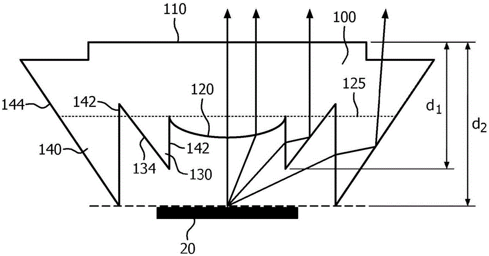
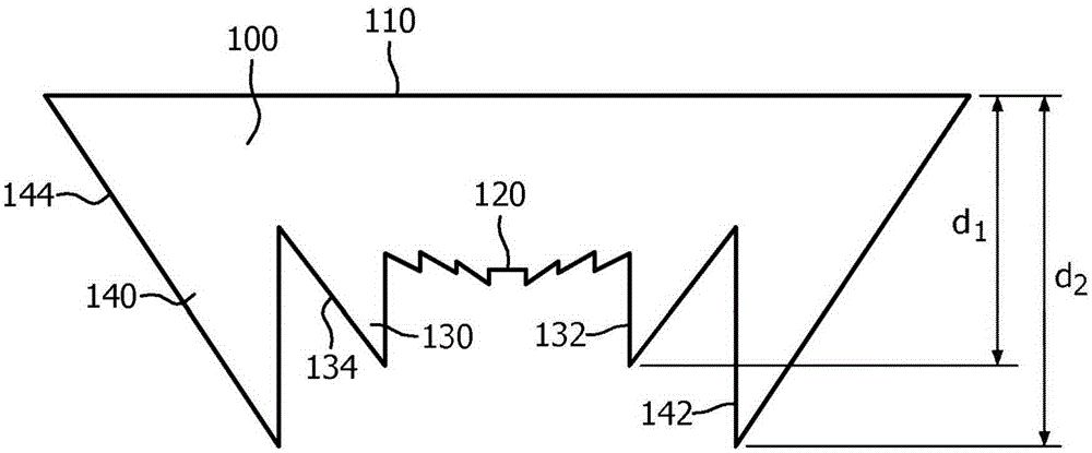
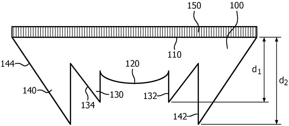
[0033] figure 1 A lens 100 according to an embodiment of the invention is schematically depicted. The lens 100 includes a light entry surface defined by a central lens portion 120 , an inner annular reflective element 130 , and an outer annular reflective element 140 defining the side surfaces of the lens 100 . The lens 100 further includes a light exit surface 110 opposite the light entry surface. In use, the light entry surface of lens 100 typically faces a light source, such as a surface comprising one or more solid state lighting (SSL) elements 20, such as light emitting diodes. In an embodiment, the inner annular reflective element 130 and the outer annular reflective element 140 are directly adjacent to each other, ie the lens 100 comprises no more...


PUM


Abstract

Disclosed is a lens (100) for a lighting device (10) comprising a solid state lighting element (20), the lens comprising a light exit surface (110); a central lens portion (120) opposite said light exit surface; an inner annular reflective element (130) opposite said light exit surface and extending away from said light exit surface by a first distance (d1 ), said inner annular reflective element delimiting said central lens portion; and a side surface defined by an outer annular reflective element (140) opposite said light exit surface and extending away from said light exit surface by a second distance (d2) that is larger than the first distance such that the outer annular reflective element extends beyond the inner annular reflective element. A lighting device such as a light bulb including such as lens is also disclosed.

Description

technical field [0001] The present invention relates to lenses for lighting devices comprising solid state lighting elements. [0002] The invention further relates to a lighting device comprising such a lens. Background technique [0003] As the population continues to increase, it is becoming increasingly difficult to both meet the world's energy needs and control carbon emissions, the greenhouse gas emissions believed to be responsible for global warming. These concerns have sparked a drive toward more efficient electricity use in an attempt to reduce energy consumption. [0004] One such area of ​​interest is lighting applications in domestic settings or in commercial settings. There is a clear trend towards replacing the notoriously energy inefficient conventional incandescent light bulbs with more energy efficient alternatives. In fact, in many jurisdictions it is illegal to manufacture and retail incandescent light bulbs, thus forcing consumers to purchase energy e...

Claims


Application Information

Patent Timeline
Patent Type & Authority Applications(China)
IPC IPC(8): F21V5/04G02B3/08G02B19/00F21K9/23F21Y115/10
Inventor 沈默李昀邹爱滨
Owner SIGNIFY HLDG BV
Learn More