Waterproof Medical Implantable Detector

An implantable and detector technology, applied in the structural form of radiation elements, radio detectors in the body, independent non-interactive antenna combinations, etc., can solve the problems of narrow antenna frequency range, limited space size, and affecting communication quality, etc., to achieve Antenna with wide frequency range, reasonable structure and high gain effect

Inactive Publication Date: 2016-12-07
马骥 +1
View PDF6 Cites 0 Cited by
  • Summary
  • Abstract
  • Description
  • Claims
  • Application Information

AI Technical Summary

Problems solved by technology

However, implantable medical diagnostic devices have certain problems, including battery life, materials, etc., but one of the biggest problems is the quality of communication. Due to the limited space of implantable medical diagnostic devices, they are often placed in The antennas in it all have shortcomings such as narrow frequency range, poor isolation, and low gain, which seriously affect the quality of communication and thus the quality of diagnosis.

Method used


Image

  • Waterproof Medical Implantable Detector
  • Waterproof Medical Implantable Detector
  • Waterproof Medical Implantable Detector

Examples


Embodiment 1

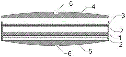
[0030] Such as Figure 1 to Figure 6 As shown, a waterproof medical implantable detector described in this embodiment includes an electronic medical detection module, a communication antenna for communicating the electronic medical detection module with the outside, and a middle shell with an H-shaped cross section. 1. Above the middle case 1, there is a first accommodation chamber for accommodating the electronic medical detection module; under the middle case 1, there is a second accommodation chamber; inside the second accommodation chamber and above the middle case 1, there are isolation plate 2; the communication antenna includes an upper antenna and a lower antenna; the lower antenna is arranged below the isolation plate 2 in the second accommodating cavity; it also includes a disc-shaped upper antenna located above the isolation plate 2 above the middle shell 1 Shell 3 ; the upper antenna is arranged in the disc-shaped upper shell 3 ; it also includes a top shell 4 for ...

Embodiment 2

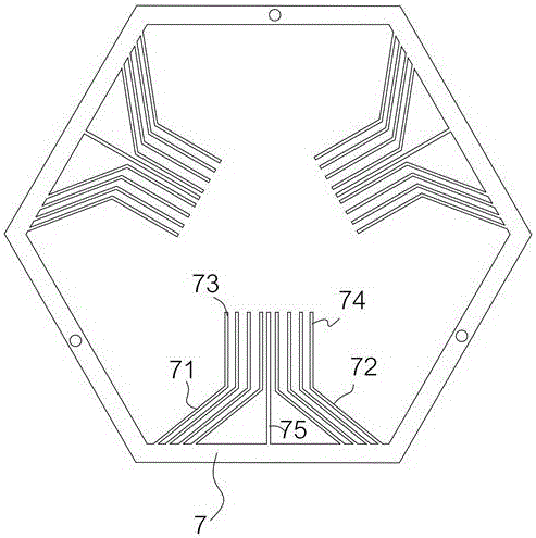
[0037]The difference between the waterproof medical implantable detector described in this embodiment and Embodiment 1 is that specific parameters are specified, so that the stability of the antenna is stronger, and the yield of good products during production is increased. Specifically, the first hypotenuse 71 The included angle with the first straight side 73 is the same as the included angle between the second hypotenuse 72 and the second straight side 74, both set as a degree; 97°≤a≤135°; the first hypotenuse 71 and the second hypotenuse The number of 72 is the same, the length of the first hypotenuse 71 is set as N, the length of the main radiating side 75 is set as M, and N=M*0.75. The above parameters are obtained through continuous testing and adjustment, which are the most stable and best performance specific parameters. The specific actual test results are calculated by HFSS15 software. The available frequency range of the antenna bandwidth of the overall system is 1....


PUM


Abstract

The invention discloses a waterproof medical implantable detector, which includes an electronic medical detection module, a communication antenna for communicating the electronic medical detection module with the outside, and a middle shell with an H-shaped cross section. There is a first accommodating chamber above for accommodating the electronic medical detection module; a second accommodating chamber is provided below the middle case; an isolation plate is provided in the second accommodating chamber and above the middle case; its structure is reasonable and harmless to the human body. Tingling feeling, reasonable internal structure setting, wide frequency range of the antenna placed inside it, good isolation and high gain; it provides a good installation module for the research and development of implantable medical diagnostic devices, each company only needs to install the One's own implantable electronic medical unit is designed to be able to be placed in the shape and thickness or size of the bottom shell, so as to achieve better communication quality.

Description

technical field [0001] The invention relates to a waterproof medical implantable detector. Background technique [0002] At present, there are many types of implanted medical devices, such as implanted cardiac pacemakers, brain pacemakers, nerve stimulators, muscle stimulators, ECG recorders, etc., and now there are diagnostic devices implanted in the human body. For real-time diagnosis of patient's heartbeat, pulsation, blood pressure or other information, like other implantable medical devices, it still needs to communicate with the outside world in order to transmit the information in real time. At present, the diagnostic device generally consists of a uniquely designed small device box and an implanted electronic medical unit in the device box; plus an antenna for connecting the implanted electronic medical unit to the outside world, the implanted electronic medical unit generally Contains detection circuit, detector, battery, etc. However, implantable medical diagnost...

Claims


Application Information

Patent Timeline
Patent Type & Authority Patents(China)
IPC IPC(8): A61B5/07A61B5/02H01Q1/22H01Q1/36H01Q1/52H01Q21/28
Inventor 任克伟马骥刘颜美刘佳路慧彬
Owner 马骥
Why Eureka
Try Eureka