
Oscillation mechanism and electric fan

A technology of electric fans and fans, applied in mechanical equipment, machines/engines, liquid fuel engines, etc., can solve the problems of large moving mechanisms, unsightly, and inability to meet customers.

Inactive Publication Date: 2016-01-27
GREE ELECTRIC APPLIANCES INC
View PDF11 Cites 2 Cited by
  • Summary
  • Abstract
  • Description
  • Claims
  • Application Information

AI Technical Summary

Problems solved by technology

Then the inclination angle of the roof fan is fixed and cannot be adjusted, resulting in the inability to adjust the air supply area and unable to meet the needs of customers
[0004] In addition, the existing shaking head mechanism is completely external, the movement mechanism is huge, and it is not beautiful

Method used


Image

  • Oscillation mechanism and electric fan
  • Oscillation mechanism and electric fan
  • Oscillation mechanism and electric fan

Examples


Embodiment Construction

[0033] The core of the present invention is to provide an oscillating mechanism, so that the inclination angle of the oscillating mechanism can be adjusted to meet the requirement of adjustable air supply area;

[0034] Another core of the present invention is to provide an electric fan.

[0035] Hereinafter, an embodiment will be described with reference to the drawings. In addition, the examples shown below do not limit the content of the invention described in the claims in any way. In addition, all the contents of the configurations shown in the following embodiments are not limited to be essential to the solutions of the invention described in the claims.

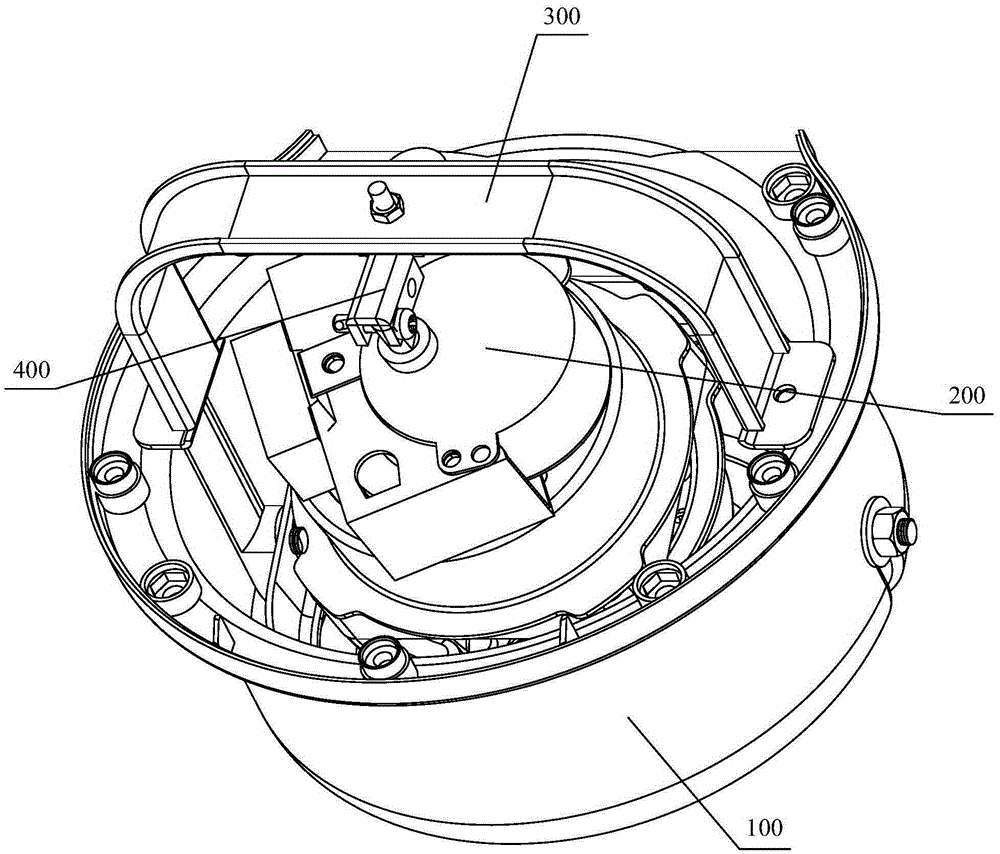
[0036] see figure 1 , figure 1 It is a structural schematic diagram of the shaking head mechanism provided by the embodiment of the present invention.

[0037] The oscillating mechanism provided by the embodiment of the present invention includes a fan housing 100 , a mounting base, a driving motor 200 , a bridge 3...


PUM


Abstract

The embodiment of the invention discloses an oscillation mechanism. The oscillation mechanism comprises a fan shell, an installation seat rotationally arranged on the fan shell, a driving motor arranged on the installation seat, a bridge connected with the fan shell and a crank, wherein the installation seat can provide the freedom degree for the driving motor when the fan shell is driven to rotate; the crank is hinged to an output shaft of the driving motor through a first hinge shaft and hinged to the bridge through a second hinge shaft; the first hinge shaft is not parallel to the second hinge shaft, and the distance between the first hinge shaft and the second hinge shaft is adjustable. The effective length of the crank is adjustable, the inclination angle of the oscillation mechanism can be further adjusted, and the requirement that an air feeding area is adjustable is met. The invention further discloses an electric fan.

Description

technical field [0001] The invention relates to the technical field of electric fans, and more specifically, relates to an oscillating mechanism and an electric fan. Background technique [0002] Existing electric fan adopts the mode of shaking head from side to side, pitching up and down or 360° circle to expand the air supply area according to its structure difference. Taking the roof fan as an example, the roof fan refers to a small fan installed on the ceiling to save space and expand the blowing range. The roof fan can automatically rotate 360 ​​degrees to supply air, and the air volume is from top to bottom, with a wide coverage and good ventilation effect. [0003] The roof fan is usually inclined at a certain angle, so that the fan blades can meet the requirements of conical air supply through the rotation of the roof fan. Then the inclination angle of the roof fan is fixed and cannot be adjusted, resulting in the inability to adjust the air supply area and unable ...

Claims


Application Information

Patent Timeline
Patent Type & Authority Applications(China)
IPC IPC(8): F04D25/10F04D29/00
Inventor 尹志雄李曙光马恒川
Owner GREE ELECTRIC APPLIANCES INC
Learn More