Draught fan, air conditioner and control method of air conditioner
An air conditioner and fan technology, applied in heating and ventilation control systems, pump control, air conditioning systems, etc., can solve problems such as difficulty in obtaining a comfortable air outlet mode, failure to meet user comfort requirements, and single air outlet direction. Achieve the effect of improving the comfort of the human body, improving the comfort of use, and meeting the needs of air conditioning comfort
- Summary
- Abstract
- Description
- Claims
- Application Information
AI Technical Summary
Problems solved by technology
Method used
Image

Examples
Embodiment 1
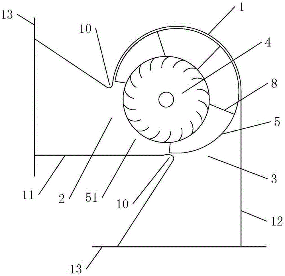
[0052] Refer below Figure 1 to Figure 4 One embodiment of the fan of the present invention will be described.
[0053] like figure 1 and figure 2As shown, the fan includes a volute 1, a side air outlet 2 is opened on the side of the volute 1, and a lower air outlet 3 is opened at the bottom. The baffle assembly can respectively open and close the side air outlet 2 and the lower air outlet 3, thereby forming different air outlet modes, that is, when the baffle assembly opens the side air outlet 2 and closes the lower air outlet 3, the side air outlet mode is formed. The baffle assembly closes the side air outlet 2, and forms the lower air outlet mode when the lower air outlet 3 is opened.
[0054] In order to improve the degree of automation, a driving device is also provided, and the driving device drives the baffle assembly to move to realize automatic switching of the air outlet mode. Of course, in order to save costs, the driving device may not be provided, and the ba...
Embodiment 2
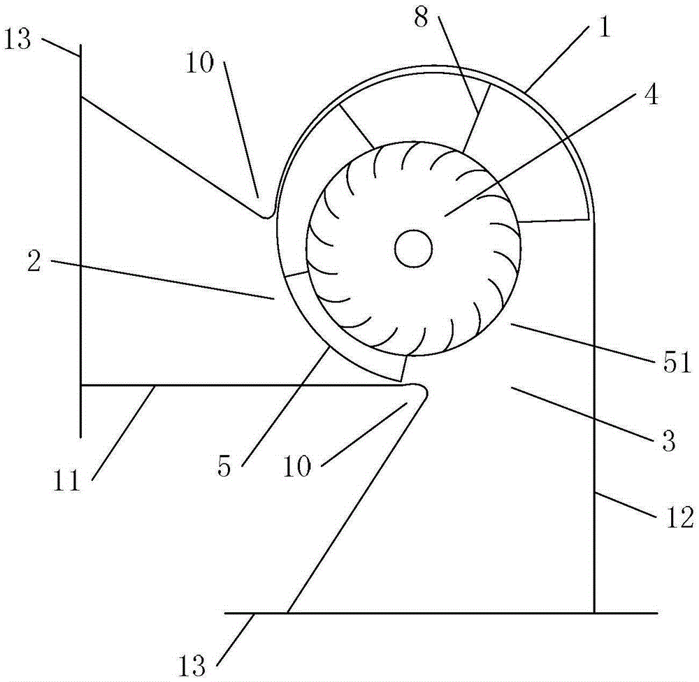
[0062] Refer below Figure 6 to Figure 9 Another embodiment of the fan of the present invention will be described.
[0063] Such as Figure 6 and Figure 7 As shown, the structure of the blower is basically the same as that of Embodiment 1, including a volute 1, a side air outlet 2 is opened on the side of the volute 1, and a lower air outlet 3 is opened at the bottom. The baffle assembly can respectively open and close the side air outlet 2 and the lower air outlet 3, thereby forming different air outlet modes. A driving device is also provided, and the baffle assembly is driven by the driving device to realize automatic switching of the air outlet mode. A centrifugal fan 4 is arranged inside the volute 1 .
[0064] The difference is that the baffle assembly of this embodiment includes a first baffle 16 for closing and opening the side air outlet 2 and a second baffle 17 for closing and opening the lower air outlet 3, and the driving device can Drive the turning of the f...
Embodiment 3
[0071] Refer below Figure 10 to Figure 11 Another embodiment of the fan of the present invention will be described.
[0072] The structure of the blower is basically the same as that of the second embodiment, including a volute 1, a side air outlet 2 is opened on the side of the volute 1, and a lower air outlet 3 is opened at the bottom. The side air outlet 2 is provided with a side air outlet main air duct 11 , and the lower air outlet 3 is provided with a lower air outlet main air duct 12 . The baffle assembly can respectively open and close the side air outlet 2 and the lower air outlet 3, thereby forming different air outlet modes. A driving device is also provided, and the baffle assembly is driven by the driving device to realize automatic switching of the air outlet mode. A centrifugal fan 4 is arranged inside the volute 1 . The baffle assembly includes a first baffle 16 for closing and opening the side air outlet 2 and a second baffle 17 for closing and opening the...
PUM
 Abstract
Description
Claims
Application Information
 - R&D
- Intellectual Property
- Life Sciences
- Materials
- Tech Scout
- Unparalleled Data Quality
- Higher Quality Content
- 60% Fewer Hallucinations
Browse by: Latest US Patents, China's latest patents, Technical Efficacy Thesaurus, Application Domain, Technology Topic, Popular Technical Reports.
© 2025 PatSnap. All rights reserved.Legal|Privacy policy|Modern Slavery Act Transparency Statement|Sitemap|About US| Contact US: help@patsnap.com