

A tightening and force limiting device and its application method
A stop device and arm technology, applied in the direction of wrenches, screwdrivers, manufacturing tools, etc., can solve the problems that cannot be reached visually and manually, and the space between the rotor disk and the journal is narrow, so as to achieve a wide range of market application prospects, ensure reliability and Reasonable and simple effect of quality and structure
- Summary
- Abstract
- Description
- Claims
- Application Information
AI Technical Summary
Problems solved by technology
Method used
Image

Examples
Embodiment Construction
[0035] The present invention will be described in further detail below in conjunction with embodiment.
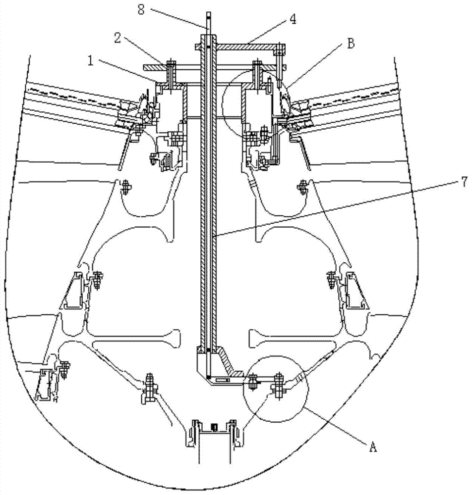
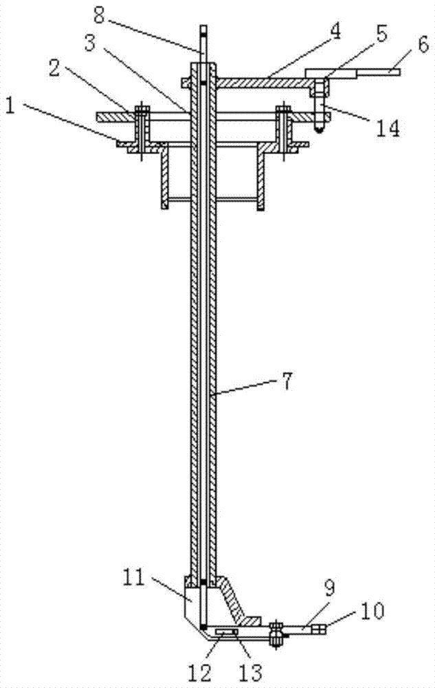
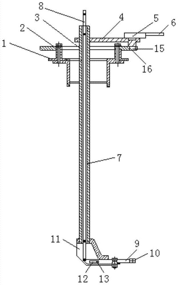
[0036] according to Figure 1 to Figure 5 As shown, a tightening and force limiting device includes: a stop device and a wrench assembly, the wrench assembly is installed on the stop device; the stop device includes: a stop sleeve 1, the stop sleeve 1 is surrounded by In the wrench assembly, a stop disc 2 is fixedly connected to the upper end of the stop sleeve 1, and a first through hole 3 is opened on the stop disc 2 for inserting the wrench assembly; the wrench assembly includes a transmission arm 4, the The lower part of one end of the transmission arm 4 is connected to one end of the stop disc 2, the upper part is provided with a positioning hole 5, and the torque wrench 6 is externally connected to the positioning hole 5, the transmission arm 4 can rotate relative to the stop disc 2, and the transmission arm 4 is in addition One end is fixedly connected to the first ...
PUM
 Abstract
Description
Claims
Application Information