
A depth measurement method and system based on shallow depth of field imaging

A technology of depth measurement and imaging, applied in the field of detection, can solve the problem that the automatic detection device cannot realize the function of depth measurement, etc.

Active Publication Date: 2017-12-05
BEIJING LUSTER LIGHTTECH
View PDF6 Cites 2 Cited by
  • Summary
  • Abstract
  • Description
  • Claims
  • Application Information

AI Technical Summary

Problems solved by technology

[0005] The present invention provides a depth measurement method and system based on shallow depth of field imaging to solve the problem that the automatic detection device in the prior art cannot realize the depth measurement function

Method used


Image

  • A depth measurement method and system based on shallow depth of field imaging
  • A depth measurement method and system based on shallow depth of field imaging
  • A depth measurement method and system based on shallow depth of field imaging

Examples


Embodiment Construction

[0032] The exemplary embodiments will be described in detail here, and examples thereof are shown in the accompanying drawings. When the following description refers to the accompanying drawings, unless otherwise indicated, the same numbers in different drawings represent the same or similar elements. The implementation manners described in the following exemplary embodiments do not represent all implementation manners consistent with the present invention. On the contrary, they are merely examples of devices consistent with some aspects of the invention as detailed in the appended claims.

[0033] The various embodiments in this specification are described in a progressive manner, and the same or similar parts between the various embodiments can be referred to each other, and each embodiment focuses on the differences from other embodiments.

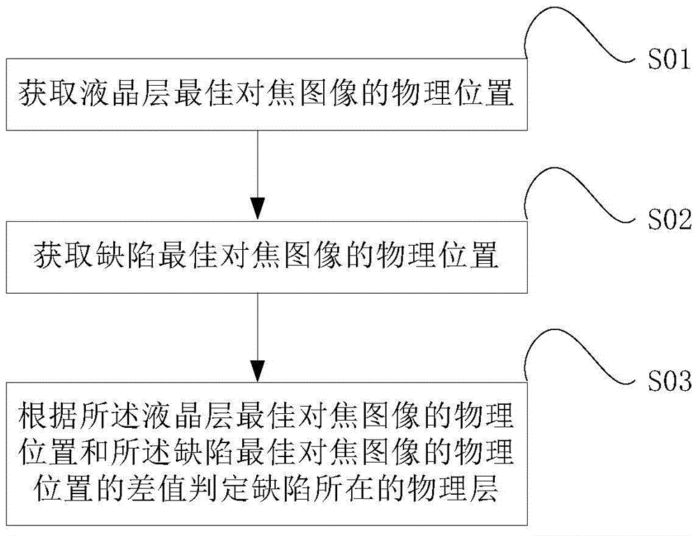
[0034] Please see figure 1 , Which shows a method flowchart of a depth measurement method based on shallow depth of field imaging provided...


PUM


Abstract

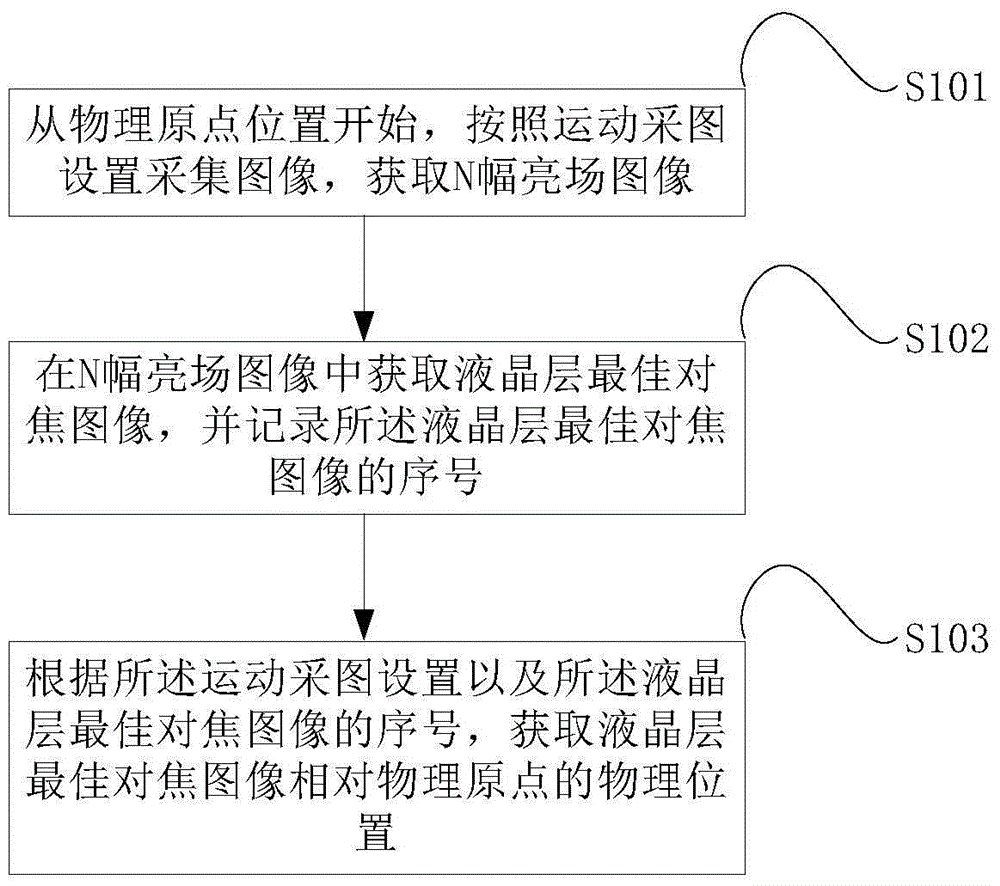
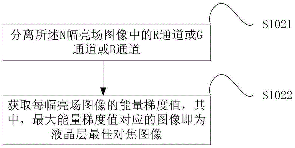
The present invention provides a depth measurement method based on shallow depth of field imaging and a corresponding system. The depth measurement method based on shallow depth of field imaging includes the following steps: obtaining the physical position of the best focus image of the liquid crystal layer; obtaining the location of the best focus image of the defect Physical position: determine the physical layer where the defect is located according to the difference between the physical position of the best focus image of the liquid crystal layer and the physical position of the best focus image of the defect. The present invention obtains the physical positions of the best focus image of the liquid crystal layer and the best focus image of the defect respectively, uses the best focus image of the liquid crystal layer as a reference plane, and determines the physical layer where the defect is located by calculating the difference between the two, and automatically detects When a defect occurs, the physical layer where the defect is located can be automatically located according to the physical position of the best focus image of the liquid crystal layer, thereby realizing the depth measurement function of the automatic detection device, which can solve the problem that the automatic detection device cannot realize the depth measurement function in the prior art .

Description

Technical field [0001] The invention relates to a detection method and system, in particular to a depth measurement method and system based on shallow depth of field imaging. Background technique [0002] The typical composition of LCD (Liquid Crystal Display) is TP (TouchPanel) glass, upper polarizer, color filter, liquid crystal layer, TFT (Thin Film Transistor) substrate, and lower polarizer from top to bottom. And the backlight. The basic principle of LCD display is to change the arrangement of the molecules inside the liquid crystal material through voltage, in order to achieve the purpose of shading and transmitting light to display different shades, patchwork images, and only need to add between two plates The ternary color filter layer can display color images. At present, LCD screens have become mainstream products in the domestic and foreign markets due to their energy saving, non-radiation, and soft screen. Therefore, the quality inspection of LCD screens has become ...

Claims


Application Information

Patent Timeline
Patent Type & Authority Patents(China)
IPC IPC(8): G02F1/13
Inventor 马增婷姚毅周钟海
Owner BEIJING LUSTER LIGHTTECH
Learn More