
Steering lock device

A technology for locking devices and locking positions, which is applied in transportation and packaging, anti-theft vehicle accessories, vehicle parts, etc., can solve problems such as easy to generate bending moments, and achieve the effect of improving work durability

Inactive Publication Date: 2016-02-10
KK TOKAI RIKA DENKI SEISAKUSHO
View PDF7 Cites 1 Cited by
  • Summary
  • Abstract
  • Description
  • Claims
  • Application Information

AI Technical Summary

Problems solved by technology

Based on this structure, since the lock is seated in contact with the flat cam of the camshaft by the elastic force of the compressed coil spring, an impact load is applied to the camshaft, thereby easily generating a bending moment.

Method used


Image

  • Steering lock device
  • Steering lock device
  • Steering lock device

Examples


Embodiment Construction

[0019] Hereinafter, preferred embodiments of the present invention will be specifically described with reference to the drawings.

[0020] (Structure of steering lock device)

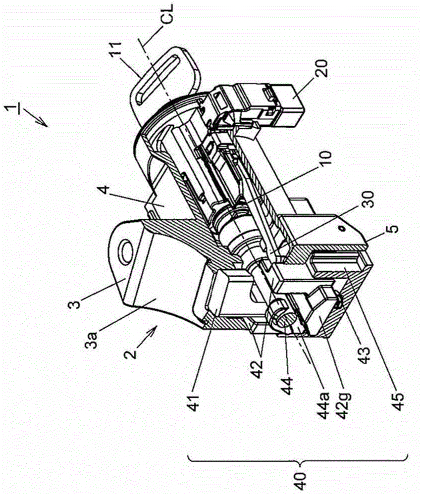
[0021] exist figure 1 In , reference numeral 1 representing the whole schematically shows the structure of a steering lock device for a vehicle. The steering lock device 1 includes a lock body 2 that is integrally processed and molded from a metal material such as die-cast zinc, for example. The lock body 2 is formed of a block-shaped cylindrical body that is long in a direction intersecting the axial direction of the steering shaft.

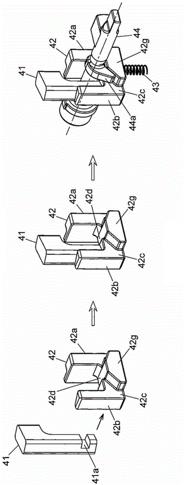
[0022] Such as figure 1 as well as image 3 As shown, the lock body 2 is provided with a lock body mounting portion 3 for being mounted on a steering column stay 51 that accommodates a steering shaft 50 in a rotatable manner. The lock body mounting portion 3 has an arc-shaped fitting recess 3 a formed at a predetermined inclination angle with respect to the central a...


PUM


Abstract

A steering lock device includes a lock body attached to a column post that rotatably supports a steering shaft, a locking bar to lock or unlock a rotation of the steering shaft by a rotating operation of a key cylinder unit housed in the lock body, a lock stopper to allow movement of the locking bar to a lock position or an unlock position, a locking lever to hold the locking bar at the lock position, and a camshaft to convert a rotary motion of the key cylinder unit into a linear motion of the lock stopper. The lock body includes a landing portion with which the lock stopper contacts so as to prevent the lock stopper from contacting with the camshaft in a lock operation that the locking bar is moved to the lock position.

Description

technical field [0001] The present invention relates to a steering lock device for locking the rotation of a steering shaft for a vehicle. Background technique [0002] A vehicle steering device includes a steering lock device that locks the rotation of a steering shaft in order to prevent a stopped vehicle from being stolen (for example, refer to Patent Document 1). [0003] The steering lock device described in the aforementioned Patent Document 1 includes: a lock lever that prohibits rotation of the steering shaft; a lock member fixed to the lock lever; a lock lever that holds the lock member; and a cam that rotates integrally with the key rotor into which the ignition key is inserted. axis. [0004] If the ignition key is pulled out when the key rotor is in the LOCK position, the locking lever is retracted from the locking member. The locking member moves integrally with the locking rod by the elastic force of the compressed coil spring, thereby abutting against and se...

Claims


Application Information

Patent Timeline
Patent Type & Authority Applications(China)
IPC IPC(8): B60R25/021
CPCB60R25/021B60R25/02118
Inventor 吉田洋为实匠河地友纪
Owner KK TOKAI RIKA DENKI SEISAKUSHO
Learn More