Double-layer columnar heat transfer device, pipeline for heat transfer of fluid substance and method

A columnar shell and columnar technology is applied in the fields of fluid material heat transfer pipes and double-layer columnar heat transfer devices, which can solve problems such as uneconomical, unsolved suggestions or solutions, and limited natural gas reserves.

Active Publication Date: 2016-02-10
杨积文 +1
View PDF11 Cites 0 Cited by
  • Summary
  • Abstract
  • Description
  • Claims
  • Application Information

AI Technical Summary

Problems solved by technology

The reserves of natural gas are limited, and the consumption of natural gas in the process of oil extraction is neither economical nor long-term for the country and the people, and is not conducive to energy conservation and emission reduction
3. Since the place where the water jacket furnace heats the oil pipeline is at the ground engineering point of oil exploitation, natural gas is used as the fuel of the water jacket furnace at the ground engineering point of oil exploitation, and very strict safety management methods must be adopted
However, inserting a heat pipe into a water heater cannot solve the problems of uneven heating of crude oil in the oil pipeline, safety management and shortage of fuel for the heating furnace, etc.
[0007] In summary, the current oil pipeline heating technology has the above defects, and no effective solutions or solutions have been seen

Method used


Image

  • Double-layer columnar heat transfer device, pipeline for heat transfer of fluid substance and method
  • Double-layer columnar heat transfer device, pipeline for heat transfer of fluid substance and method
  • Double-layer columnar heat transfer device, pipeline for heat transfer of fluid substance and method

Examples


Embodiment Construction

[0045] The technical solutions of the present invention are described below by means of drawings and specific embodiments.

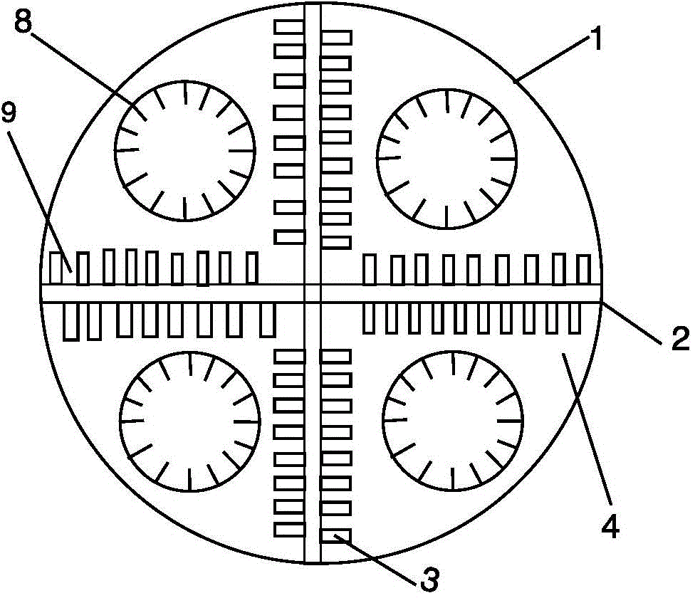
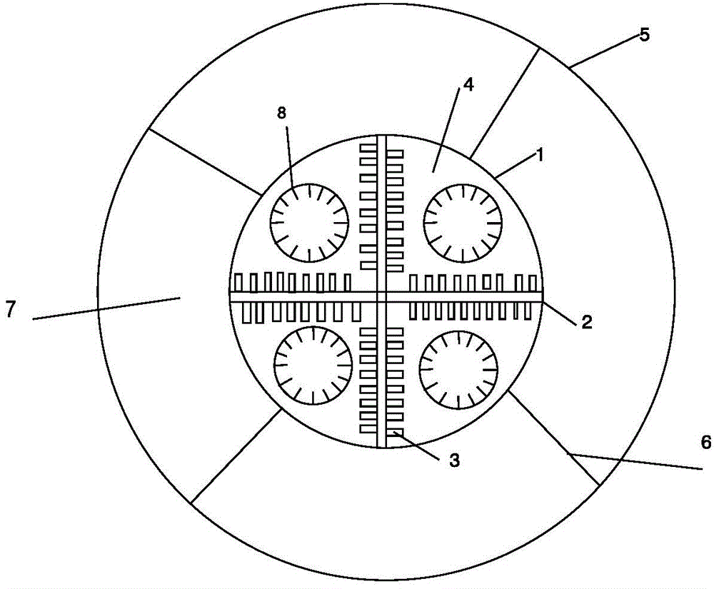
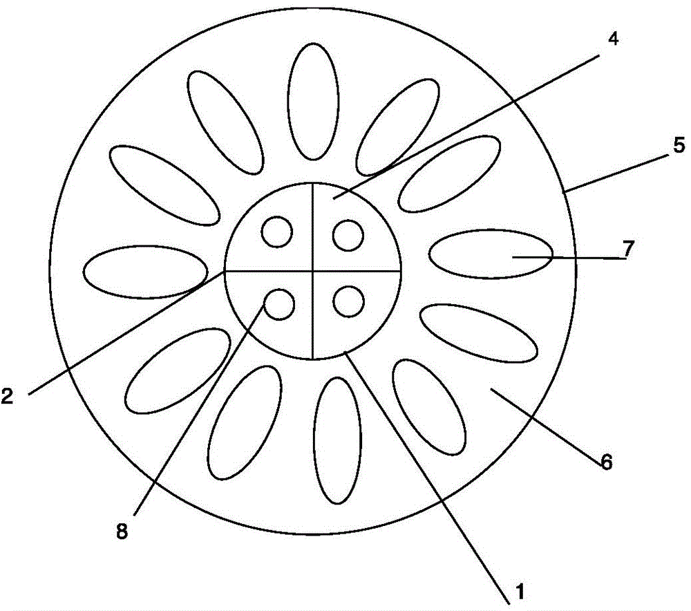
[0046] Such as figure 1 As shown, one of the most important aspects of the present invention is to provide a double-layer cylindrical heat transfer device, which is characterized in that: it includes a heat-conducting cylindrical shell 1 and a partition plate 2; the inner cavity of the heat-conducting cylindrical shell 1 It is a closed space; the partition plate 2 divides the inner cavity of the heat-conducting cylindrical shell 1 into a plurality of chambers 4 parallel to the axial direction of the heat-conducting cylindrical shell; Filled with working fluid; the inner wall of the chamber 4 is sequentially provided with a number of micro-fins 3 made of heat-conducting materials, and an array of capillary micro-grooves 9 is formed between adjacent micro-fins 3 . The fine grooves 9 are arranged in a way that is conducive to reducing the resistance of th...


PUM


Abstract

The invention discloses a double-layer columnar heat transfer device, a pipeline for heat transfer of a fluid substance and a method and belongs to a pipeline heating technology. The double-layer columnar heat transfer device comprises a heat conductive columnar casing 1 and partition boards 2, and an inner cavity of the heat conductive columnar casing 1 is closed space and divided by the partition boards 2 into a plurality of cavities 4 parallel to the axial direction of the heat conductive columnar casing; the cavities 4 are filled with a working medium; a plurality of microfins 3 made of a heat conduction material are arranged on the inner walls of the cavities 4 in sequence, arrayed capillary microgrooves 9 are formed between the adjacent microfins 3 and are arranged in a mode which is beneficial to reduction of resistance received by the working medium flowing in the cavities 4; columnar heat pipes are further inserted in the cavities, and arrayed microfins are arranged on the inner walls of the columnar heat pipes. The invention further provides the pipeline based on the columnar heat transfer device and the heating method.

Description

technical field [0001] The invention relates to pipeline heating technology, in particular to a double-layer columnar heat transfer device, a pipeline and a method for fluid material heat transfer. Background technique [0002] In many industrial fields, on the one hand, there is a demand for heating or heat exchange of fluid substances such as oil, water, and gas. On the other hand, a lot of industrial waste heat will be generated, which can be recycled to save energy. Heat transfer equipment for these two needs generally needs to be relatively large, capable of smooth heat transfer and fluid delivery, and the temperature is stable within a certain range during the heat transfer process to ensure safety. [0003] For example, during the process of transporting viscous oil from the underground to the ground, the oil will become very thick at the ground temperature and it is difficult to effectively transport it. Therefore, it is necessary to heat the pipeline at the wellhea...

Claims


Application Information

Patent Timeline
Patent Type & Authority Applications(China)
IPC IPC(8): F28D15/04F17D1/18
Inventor 杨积文康斌
Owner 杨积文
Why Eureka
Try Eureka