Improved mounting and locking device for circuit board

A locking device and circuit board technology, applied in metal processing, metal processing equipment, manufacturing tools, etc., can solve the problems of extra space cost, increased circuit board production cost, inconvenient centralized storage and transportation, etc.

A locking device and circuit board technology, applied in metal processing, metal processing equipment, manufacturing tools, etc., can solve the problems of extra space cost, increased circuit board production cost, inconvenient centralized storage and transportation, etc.

CN105345446AInactive Publication Date: 2016-02-24尚庆光

Image

  • Improved mounting and locking device for circuit board

Examples


Embodiment Construction

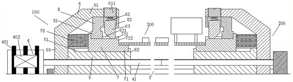
[0009] Combine below figure 1 The present invention will be described in detail.

[0010] According to an embodiment, an improved installation and locking device for the circuit board 300 includes a drive motor 4 fixedly connected to the base frame, a drive screw 41 power-coupled with the drive motor 4, and a drive screw 41 on the drive screw 41. The left mounting assembly 100 and the right mounting assembly 200 are respectively driven by two segments of screw threads in opposite directions, and the guide rail 3 which is fixedly connected to the base frame and guides the left mounting assembly 100 and the right mounting assembly 200, wherein, The left mounting assembly 100 and the right mounting assembly 200 are arranged symmetrically, and each includes: a threaded base 5 threadedly fitted with the drive screw 41, a fixing frame 6 fixedly connected to the outer end of the threaded base 5, In the rail groove 51 on the upper side of the threaded base 5, a slidable mounting bearing...


PUM


Abstract

An improved mounting and locking device for a circuit board comprises a driving motor (4), a driving screw (41), a left mounting component (100), a right mounting component (200), and a guiding part (3), wherein the driving motor (4) is fixedly connected with a base frame, the driving screw (41) is in power connection with the driving motor (4), the left mounting component (100) and the right mounting component (200) are respectively driven by two sections of threads which are positioned on the driving screw (41) and opposite in rotating directions, and the guiding part (3) is fixedly connected with the base frame and used for guiding the left mounting component (100) and the right mounting component (200), and the left mounting component (100) and the right mounting component (200) are symmetrically arranged.

Description

Technical field [0001] The invention relates to the field of circuit boards, in particular to an improved mounting and locking device for circuit boards. Background technique [0002] The installation and removal of the circuit board will affect the stability and reliability of the operation of the equipment using the circuit board, and will affect its maintainability. The current circuit board installation often adopts opening holes on the circuit board and inserting the circuit board through a fixed post arranged on the equipment rack. The fixed post has an elastic contraction locking structure or an external thread capable of tightening a nut. Fix the circuit board in place and be able to disassemble the circuit board to facilitate maintenance during use. [0003] However, this installation mode first requires opening a through hole on the circuit board, which will affect the wiring layout of the circuit board itself, and will affect the line stability of the wiring around the ...

Claims


Application Information

Patent Timeline
24 Feb 2016
Publication
CN105345446A
IPC
B23P19/04
CPC
B23P19/04; B23P19/006
Inventors
尚庆光