Rotary compressor

A technology of rotary compressor and rotary shaft, which is used in rotary piston machinery, rotary piston pump, mechanical equipment, etc., can solve the problem of inability to ensure the tightness of the cylinder chamber, achieve simplified structure and assembly, reduce leakage loss, The effect of reducing the number of components

Active Publication Date: 2016-03-09
MITSUBISHI HEAVY IND THERMAL SYST
View PDF7 Cites 9 Cited by
  • Summary
  • Abstract
  • Description
  • Claims
  • Application Information

AI Technical Summary

Problems solved by technology

However, this cannot ensure the sealing of the cylinder chamber. Therefore, as shown in Patent Document 1, there is provided a rotary compressor having a structure in which the rotating shaft can be divided by the intermediate shaft portion between the eccentric shaft portions, and the partition plate can be inserted. After the intermediate shaft part, the divided rotary shaft is integrally combined

Method used


Image

  • Rotary compressor
  • Rotary compressor
  • Rotary compressor

Examples


no. 1 Embodiment approach

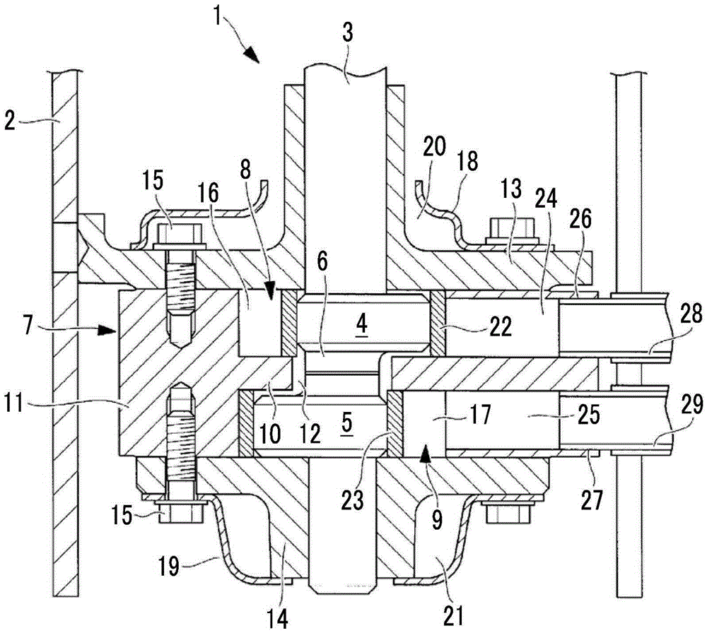
[0035] Below, use figure 1 , the first embodiment of the present invention will be described.

[0036] figure 1 A longitudinal sectional view of the rotary compressor according to the first embodiment of the present invention is shown in .

[0037] The rotary compressor 1 of the present embodiment can be applied to a single-stage multi-cylinder rotary compressor or a multi-stage rotary compressor, and here, a two-cylinder type hermetic rotary compressor including two cylinders is exemplified. This rotary compressor 1 is configured to include a hermetic casing 2, and a rotary compression mechanism 7 driven via a rotary shaft (crankshaft) 3 is provided in the hermetic casing 2 by an electric motor (not shown) provided in an upper portion of the hermetic casing 2. lower part.

[0038] The upper part of the rotating shaft (crankshaft) 3 is combined with the rotor of the electric motor, and is rotated by the electric motor, and the lower part is provided with a first eccentric s...

no. 2 Embodiment approach

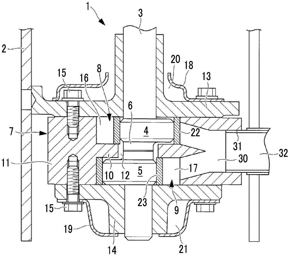
[0059] Next, use figure 2 A second embodiment of the present invention will be described.

[0060] In this embodiment, the configurations of the suction port 30 and the suction pipe connection hole 31 are different from those of the first embodiment described above. The other points are the same as those of the first embodiment, and thus description thereof will be omitted.

[0061] In this embodiment, if figure 2 As shown, a large common suction port 30 that is branched across the partition plate 10 and communicated with a plurality of cylinder chambers 16 and 17 is provided, and a large common suction port 30 that communicates with the suction port 30 is provided. A single thick suction pipe 32 can be connected to the common suction pipe connection hole 31 .

[0062] In this way, the suction port 30 is set as a common suction port 30 that is branched across the partition plate 10 and communicates with the plurality of cylinder chambers 16, 17, and a common suction port ...

no. 3 Embodiment approach

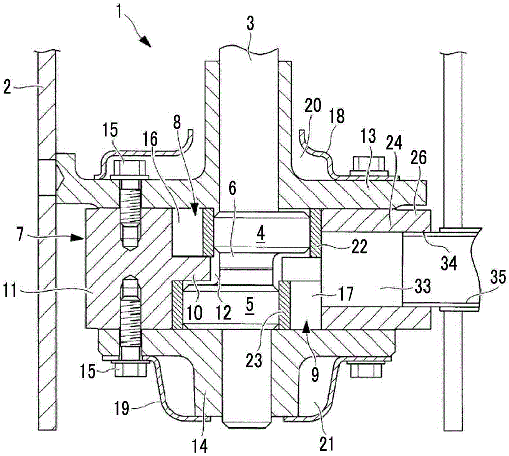
[0065] Next, use image 3 A third embodiment of the present invention will be described.

[0066] In this embodiment, the configurations of the suction port 33 and the suction pipe connection hole 34 are different from those of the first embodiment described above. The other points are the same as those of the first embodiment, and thus description thereof will be omitted.

[0067] In this embodiment, if image 3 As shown, a large common suction port 33 communicating with the plurality of cylinder chambers 16 and 17 across the partition plate 10 is provided, and a large common suction pipe communicating with the suction port 33 is provided. The connection hole 34 allows connection of one relatively thick suction pipe 35 .

[0068]In this way, the suction port 33 is set as one common suction port 33 communicating with the plurality of cylinder chambers 16, 17 across the partition plate 10, and one common suction piping connection hole is provided in communication with the su...


PUM


Abstract

Provided is a rotary compressor that: removes limitations such as restrictions on intake pipe diameter, seal limits on a separator plate, and assembly limits on a rotating shaft; makes possible a limit design exceeding that of the present situation; and achieves increased efficiency, a reduced number of components, and a simplified assembly. A multi-cylinder rotary compressor (1) provided with a plurality of cylinders (8, 9), wherein a rotating shaft (3) provided with a plurality of eccentric shaft parts (4, 5) at prescribed intervals in an axial direction is divided by a center shaft part (6) between the eccentric shaft parts (4, 5) into a rotating shaft having a divided structure that can be integrally linked, and the plurality of cylinders (8, 9) have cylinder chambers (16, 17) formed in both end surfaces, resulting in an integrated-structure cylinder (11) in which a separator plate (10) partitioning the cylinder chambers (16, 17) is integrally formed in the center.

Description

technical field [0001] The present invention relates to a multi-cylinder rotary compressor including a plurality of cylinders. Background technique [0002] In a single-stage multi-cylinder rotary compressor or a multi-stage rotary compressor, a plurality of cylinders are arranged in the direction of the rotation axis, a partition plate is inserted between the plurality of cylinders, and one end of each cylinder is closed by the partition plate , the other end is closed by each bearing component, thereby forming a plurality of cylinder chambers. Further, a rotor (piston) that rotates along the inner peripheral surface of the cylinder chamber is rotatably provided on an eccentric shaft portion of a rotating shaft (crank shaft), and compression operation is performed by the eccentric rotation of the rotor. [0003] In this type of rotary compressor, it is necessary to pass the eccentric shaft portion of the rotary shaft through the through hole of the partition plate during a...

Claims


Application Information

Patent Timeline
Patent Type & Authority Applications(China)
IPC IPC(8): F04C23/00F04C18/356
CPCF04C18/356F04C23/001F04C29/0057F04C2240/60F04C2250/101
Inventor 小川真江崎郁男宇野将成
Owner MITSUBISHI HEAVY IND THERMAL SYST
Why Eureka
Try Eureka