Transmission circuit, wireless communication apparatus and timing adjustment method for transmission circuit

A technology for sending circuits and circuits, which is applied to the layout of negative feedback circuits, components of amplifiers, and synchronization devices, etc., which can solve problems such as signal quality degradation, unsolvable problems, discontinuous adjustments, etc., and achieve area or power consumption suppression , Improve the output parasitic characteristics, improve the effect of quality

Inactive Publication Date: 2009-09-16
HITACHI LTD
View PDF4 Cites 0 Cited by
  • Summary
  • Abstract
  • Description
  • Claims
  • Application Information

AI Technical Summary

Problems solved by technology

[0009] However, in general, the delay occurs in a minute unit of less than one clock, and it fluctuates in time due to external factors such as temperature changes.
[0016] if used Figure 8 In the method shown, it is also possible to adjust the delay that occurs in less than one clock unit, but there is such a problem, that is, because the adjustment amount is discontinuous, on the basis of residual quantization error in the adjustment amount, Affected by the group delay characteristic of the filter, the amount of delay varies with the frequency, deteriorating the signal quality
In addition, this is a function for matching the timing of the transmission signal and the feedback signal. Since it does not have a function to adjust the delay difference between the two components of the transmission signal, it cannot solve the above-mentioned problems of the EER method.

Method used


Image

  • Transmission circuit, wireless communication apparatus and timing adjustment method for transmission circuit
  • Transmission circuit, wireless communication apparatus and timing adjustment method for transmission circuit
  • Transmission circuit, wireless communication apparatus and timing adjustment method for transmission circuit

Examples


Embodiment Construction

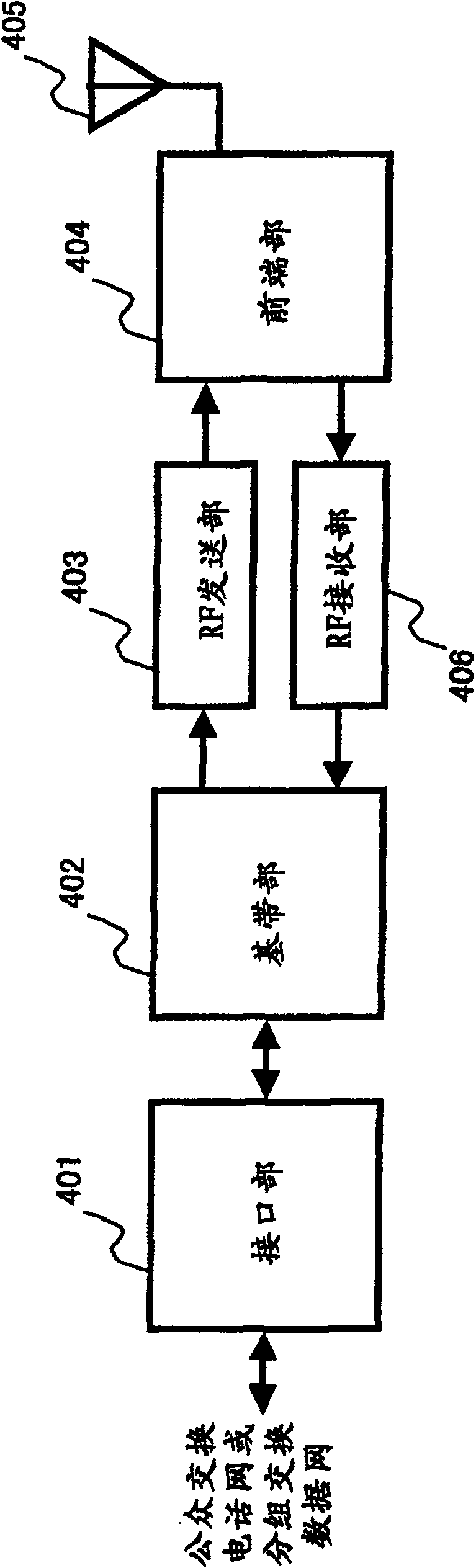
[0032] figure 1 It is a block diagram showing a general configuration of a transceiver of a radio base station.

[0033] The transceiver is composed of the following components, namely: the interface part 401 connected with the public switched telephone network or the packet switched data network; the baseband part 402 for digital modulation and demodulation; The signal is converted into an analog signal, and the frequency is converted from the baseband frequency band to the high frequency (RF) frequency band, and the output power is amplified; the front end part 404 composed of a filter and an antenna transceiver switch; the antenna 405 and the RF receiving part 406, from the RF frequency band Perform frequency conversion to the baseband frequency band, use filter conversion to remove out-of-band noise components, and convert it into a digital signal. The present invention particularly relates to the configuration of the RF transmission unit 403 .

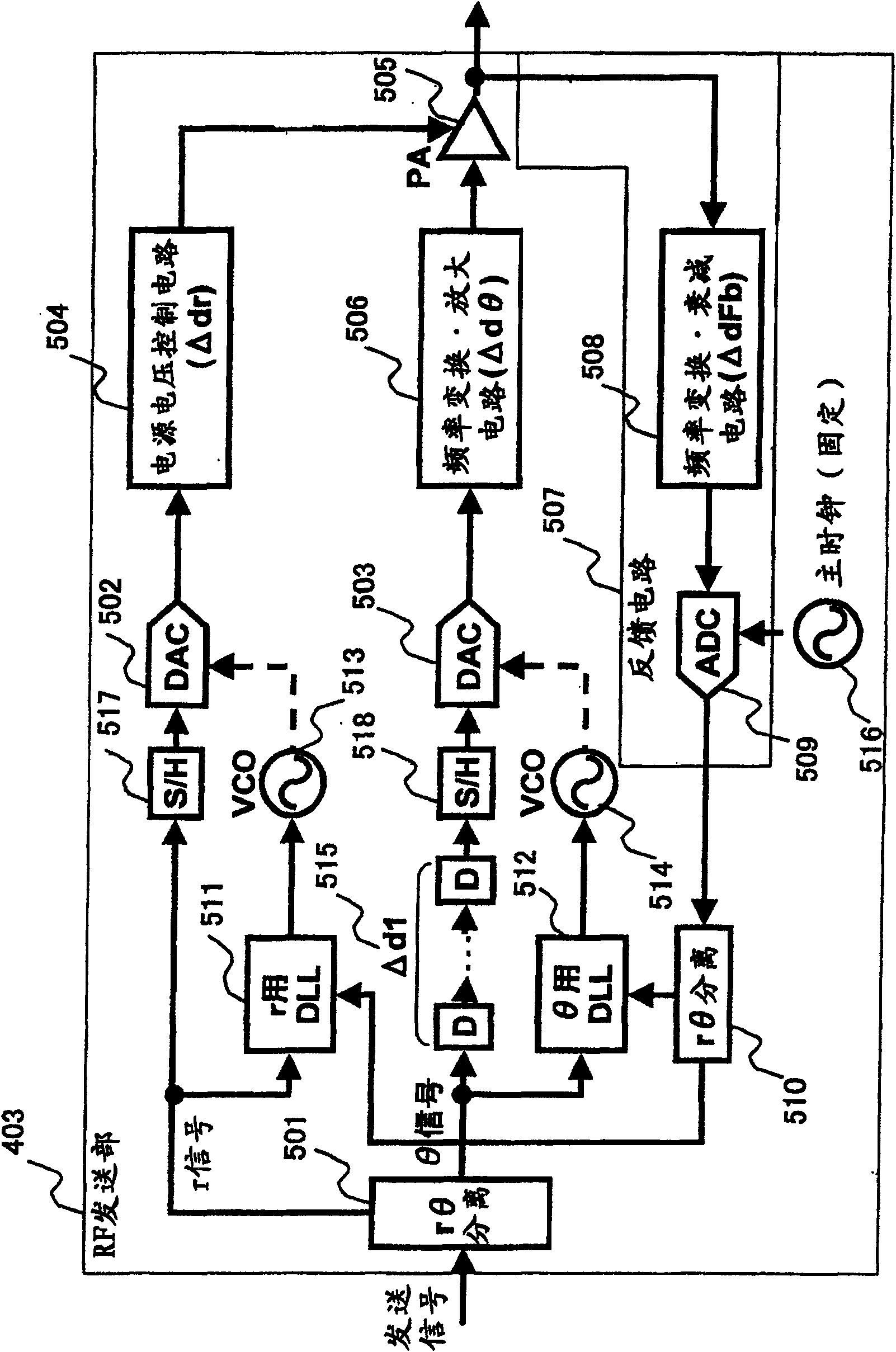
[0034] figure 2 It is...


PUM


Abstract

The invention provides a timing adjustment method of a wireless communication device. In a wireless communication device, the delay difference between two signal paths that are modulated and synthesized by paths having different delay amounts, such as an I signal and a Q signal of a quadrature modulation method, and an r signal and a θ signal of an EER method, is adjusted. , thereby improving the linearity of the transmitted signal. It has a DA converting circuit, a combining circuit, a distributing circuit, an AD converting circuit, an oscillating circuit, a first separating circuit and a comparing circuit, wherein the oscillating circuit controls its output according to the comparison result by the comparing circuit.

Description

technical field [0001] The present invention relates to a transceiver with a function of adjusting the timing of a transmission signal by means of a closed-loop feedback control, and in particular to a transmission timing adjustment of an r (amplitude) component and a θ (phase) component using an EER method Transceiver. Background technique [0002] In transmitters installed in base stations and terminals of wireless communication systems including mobile phones, a method has been developed that separates transmission signals into two systems, processes them separately, synthesizes them again, and transmits the output. As such a method, for example, a method of separating and processing a transmission signal into an I signal and a Q signal, or an EER (Envelope Elimination and Restoration) method of separating and processing a transmission signal into an r (amplitude) component and a θ (phase) component are known. [0003] However, in the case of separating and processing th...

Claims


Application Information

Patent Timeline
Patent Type & Authority Patents(China)
IPC IPC(8): H04B1/04H03F1/32H03G3/30H04L7/02H04L27/00
CPCH03F1/3282H03F1/3247H03F3/189H04B2001/0433H04B1/0475H04L7/0054H04B1/0483H03F3/24H03F2200/451H03F1/34H04B1/04H04L7/02H04L27/00
Inventor 鈴木芽衣堀一行矢野隆
Owner HITACHI LTD
Why Eureka
Try Eureka