Compressor

A technology of a compressor and a compression mechanism, applied in the field of compressors, can solve problems such as the reduction of the efficiency of the motor part, and achieve the effects of suppressing heating and high volume efficiency

Active Publication Date: 2013-12-04
PANASONIC CORP
View PDF9 Cites 0 Cited by
  • Summary
  • Abstract
  • Description
  • Claims
  • Application Information

AI Technical Summary

Problems solved by technology

[0007] However, in the conventional structure, there is the following technical problem: the high-temperature and high-pressure refrigerant gas compressed by the compression mechanism part flows through the motor part, so the motor part is heated by the refrigerant gas, causing the efficiency of the motor part to decrease.

Method used


Image

  • Compressor
  • Compressor
  • Compressor

Examples


Embodiment approach 1

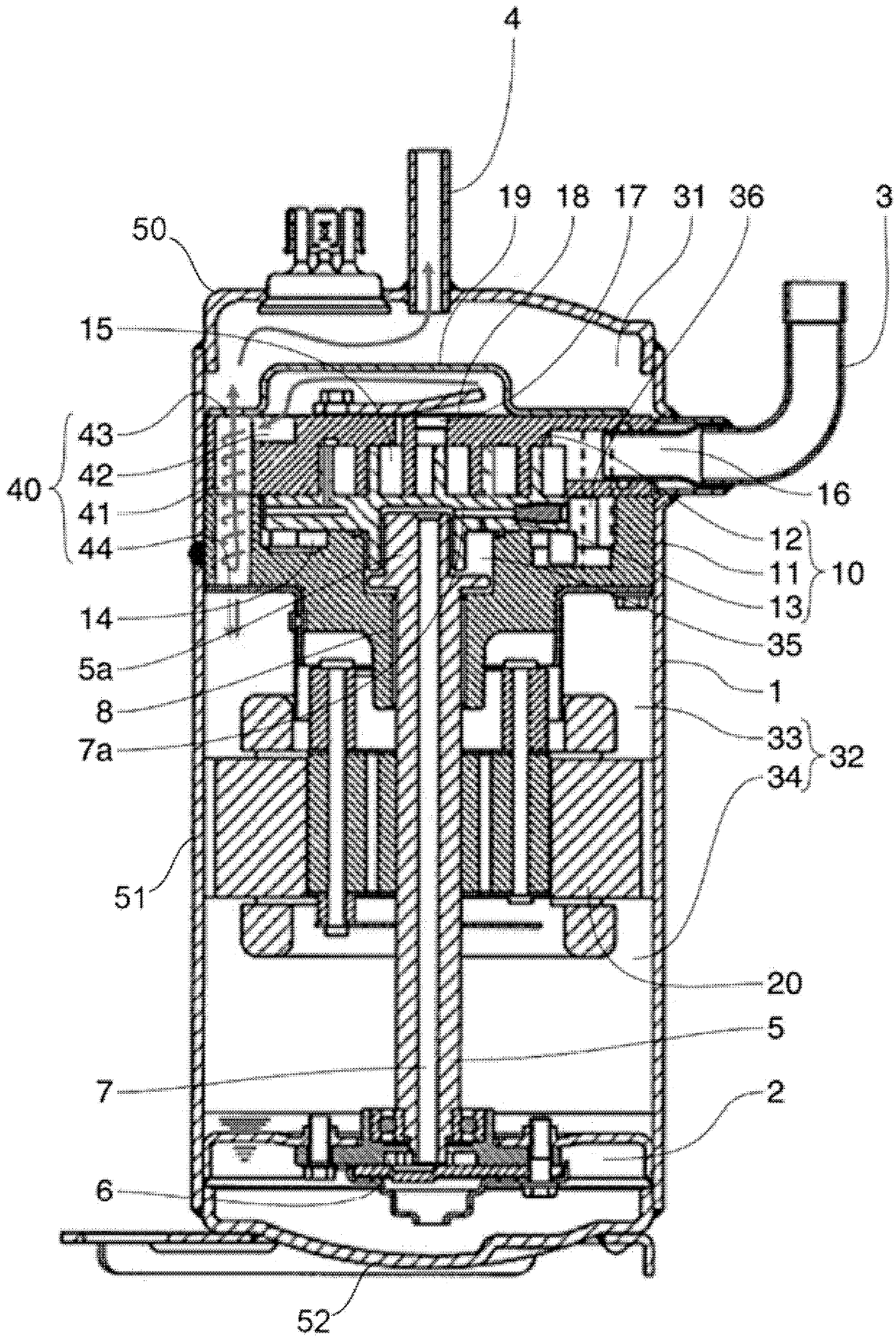
[0055] figure 1 It is a longitudinal cross-sectional view of the compressor of Embodiment 1 of this invention. Such as figure 1 As shown, the compressor of the present embodiment includes a compression mechanism section 10 that compresses refrigerant gas and a motor section 20 that drives the compression mechanism section 10 in the airtight container 1. The inside of the airtight container 1 is partitioned into one container inner space 31 and the other container inner space 32 by the compression mechanism 10. In addition, a motor unit 20 is arranged in the space 32 in the other container. In addition, the other container inner space 32 is partitioned into the compression mechanism side space 33 and the oil storage side space 34 by the motor unit 20. In addition, the oil storage portion 2 is arranged in the oil storage side space 34. In the airtight container 1, the suction pipe 3 and the discharge pipe 4 are fixed by welding. The suction pipe 3 and the discharge pipe 4 comm...

Embodiment approach 2

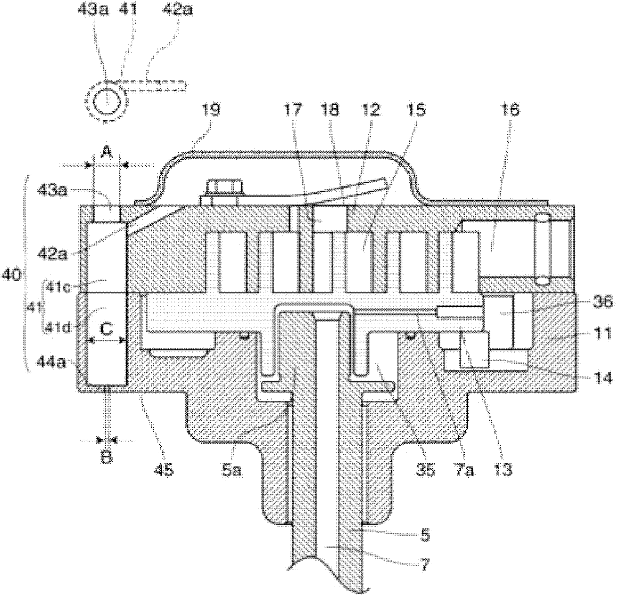
[0073] image 3 It is an enlarged cross-sectional view of a main part of a compression mechanism of a compressor according to Embodiment 2 of the present invention. The basic structure of this embodiment is the same as figure 1 The same, so the description is omitted. In addition, for figure 1 with figure 2 The same structure as described is assigned the same reference numeral, and a part of the description is omitted.

[0074] In this embodiment, a stepped hole processing is performed on the outer periphery of the fixed scroll 12, thereby forming the first cylindrical space 41c and the delivery port 43a. The first cylindrical space 41 c is formed by processing an impermeable hole from an end surface on the fixed surface side (end surface on the overlap portion side) of the main bearing member 11. The delivery port 43a is set higher than the end surface on the side opposite to the fixed side of the main bearing member 11 (the end on the side of the overlap portion) or from the ...

Embodiment approach 3

[0077] Figure 4 It is an enlarged cross-sectional view of a main part of a compression mechanism of a compressor according to Embodiment 3 of the present invention. The basic structure of this embodiment is the same as figure 1 The same, so the description is omitted. In addition, for figure 1 with figure 2 The same structure as described is assigned the same reference numeral, and a part of the description is omitted.

[0078] In this embodiment, a cylindrical delivery pipe 46 is provided in the cylindrical space 41. One end 46 a of the delivery pipe 46 forms a delivery port 43, and the other end 46 b of the delivery pipe 46 is arranged in the cylindrical space 41. In addition, in this embodiment, the other end 46b of the delivery pipe 46 extends into the second cylindrical space 41b.

[0079] An annular space 46c is formed on the outer circumference of the delivery pipe 46, and the inflow portion 42 opens in the annular space 46c. At one end 46a of the delivery pipe 46, a fl...


PUM


Abstract

Provided is a compressor equipped with an oil separation mechanism unit (40) that separates oil from a refrigerant gas discharged from a compression mechanism part (10), with the oil separation mechanism unit (40) having: a cylindrical space (41) in which the refrigerant gas is caused to rotate; an inflow part (42) that introduces the refrigerant gas discharged from the compression mechanism part (10) into the cylindrical space (41); a delivery outlet (43) that delivers the refrigerant gas, from which the oil has been separated, from the cylindrical space (41) to one space (31) within a container; and a discharge port (44) that discharges the separated oil from the cylindrical space (41) to the other space (32) within the container. The delivery outlet (43) is provided with an impactor (49) with a prescribed distance therebetween. Thus, the electric motor part is highly efficient, and the compressor has improved volumetric efficiency and low oil circulation.

Description

Technical field [0001] The present invention relates to a compressor provided with an oil separation mechanism that separates oil from refrigerant gas discharged from the compression mechanism. Background technique [0002] In the prior art, compressors used in air conditioners, cooling devices, etc., generally have a compression mechanism part and a motor part that drives the compression mechanism part in a housing, and the compression mechanism part performs refrigerant gas return from the refrigeration cycle. Compressed and sent to the refrigeration cycle. Generally speaking, the refrigerant gas compressed by the compression mechanism temporarily flows around the motor to cool the motor, and then is sent to the refrigeration cycle from the discharge pipe provided in the housing (for example, refer to Patent Literature 1). That is, the refrigerant gas compressed by the compression mechanism is discharged from the discharge port to the discharge space. After that, the refrige...

Claims


Application Information

Patent Timeline
IPC IPC(8): F04B39/04F04C29/02
CPCF04C29/026F04C23/008F04B39/04F04C18/0215
Inventor 河野博之二上义幸中本达也今井悠介作田淳森本敬
Owner PANASONIC CORP
Why Eureka
Try Eureka