Fuel injection system for an internal combustion engine

a fuel injection system and internal combustion engine technology, applied in the direction of fuel injecting pumps, machines/engines, electric control, etc., can solve the problems of poor efficiency of high-pressure pumps and worsen the efficiency of fuel injection systems, and achieve the effect of improving efficiency, simplifying the layout of the fuel injection system, and improving the efficiency of the high-pressure pump

Inactive Publication Date: 2005-12-20
ROBERT BOSCH GMBH
View PDF9 Cites 25 Cited by
  • Summary
  • Abstract
  • Description
  • Claims
  • Application Information

AI Technical Summary

Benefits of technology

[0005]The fuel injection system of the invention has the advantage over the prior art that because the control valve is embodied as a clocking valve, throttling of the fuel delivered to the intake side of the high-pressure pump does not occur, and thus the filling and the volumetric efficiency of the high-pressure pump are improved. Moreover, the inlet from the feed pump to the intake side of the high-pressure pump can be closed completely in a simple way so that no additional provisions are necessary for assuring the zero pumping of the high-pressure pump; the layout of the fuel injection system is thus simplified and its efficiency is improved.
[0006]Other advantageous features and refinements of the fuel injection system of the invention are disclosed. One embodiment assures that excess fuel pumped by the feed pump and not delivered to the intake side of the high-pressure pump can be carried away, while another embodiment assures adequate lubrication of the drive mechanism of the high-pressure pump even when the pump is not pumping any fuel. The invention makes it possible to ventilate the communication between the feed pump and the intake side of the high-pressure pump.

Problems solved by technology

The high-pressure pump has poor efficiency as a result.
However, it cannot be assured that the inlet for fuel from the feed pump to the high-pressure pump will be completely closed by the regulating valve, and thus additional provisions are necessary to carry away fuel, pumped by the feed pump and passing through the regulating valve, so that the fuel will not be pumped into the reservoir by the high-pressure pump and so that the zero pumping state will be achieved.
These additional provisions in turn worsen the efficiency of the fuel injection system, since some of the fuel pumped by the feed pump flows constantly out in the form of a leakage flow.

Method used


Image

  • Fuel injection system for an internal combustion engine
  • Fuel injection system for an internal combustion engine
  • Fuel injection system for an internal combustion engine

Examples


Embodiment Construction

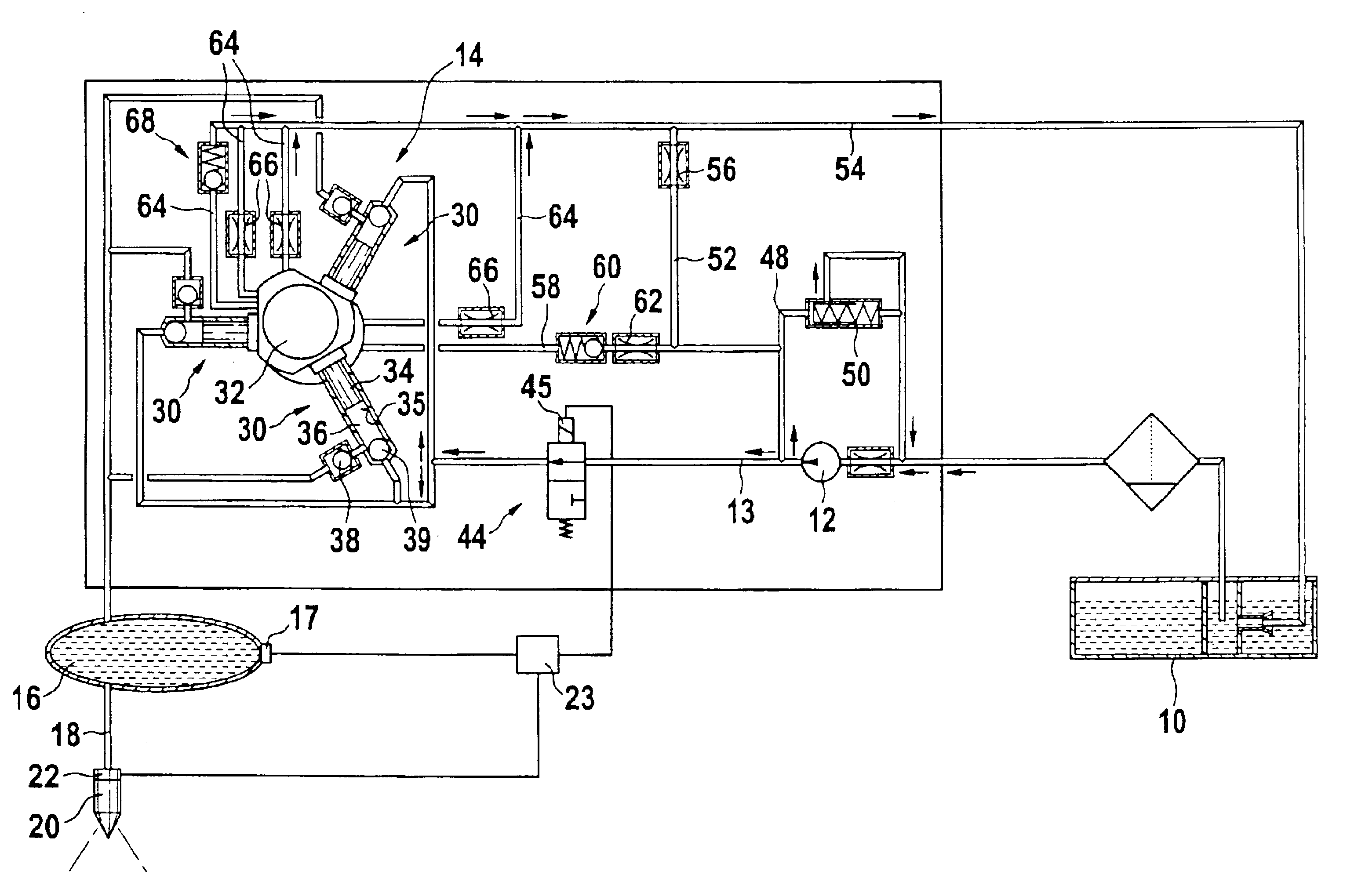
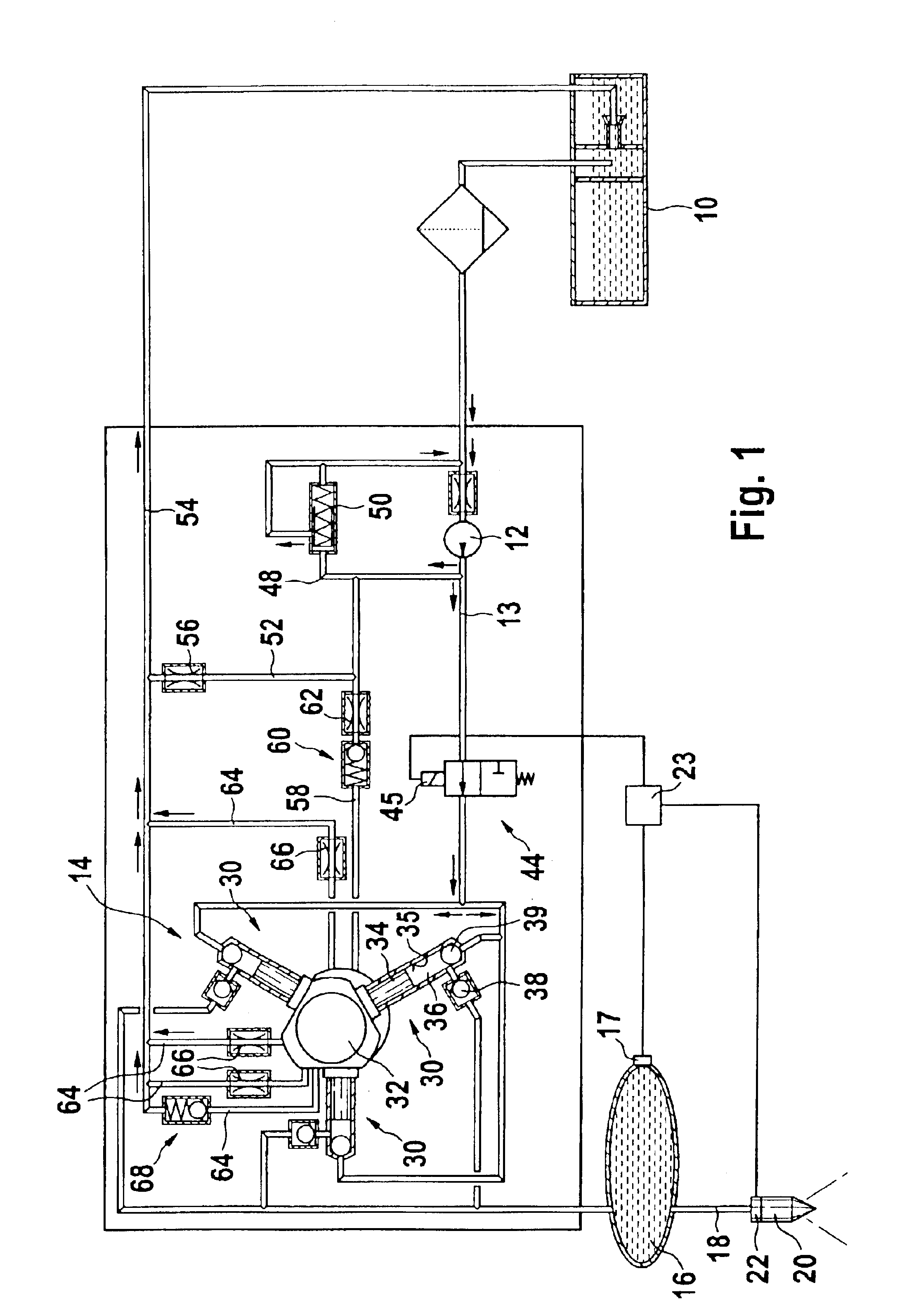
[0010]In FIG. 1, a fuel injection system for an internal combustion engine, for instance of a motor vehicle, is shown. The engine is preferably a self-igniting engine and has one or more cylinders. The motor vehicle has a fuel tank 10, in which fuel for operating the engine is kept on hand. The fuel injection system has a feed pump 12, by which fuel from the fuel tank 10 is pumped via a communication 13 to the intake side of a high-pressure pump 14. The high-pressure pump 14 pumps fuel into a reservoir 16, which can be embodied in tubular form, for instance, or in some arbitrary other shape. From the reservoir 16, lines 18 lead to injectors 20 disposed on the cylinders of the engine. At each of the injectors 20 there is a respective electrical control valve 22, by which an opening of the injectors is controlled, in order to effect a fuel injection through the respective injector 20 or to prevent a fuel injection. The control valves 22 are triggered by an electronic control unit 23, ...


PUM


Abstract

The fuel injection system has a high-pressure pump, by which fuel is pumped into a reservoir, with which injectors disposed on cylinders of the engine communicate. A feed pump pumps fuel out of a fuel tank to the high-pressure pump and a fuel metering device triggered by a control unit and disposed between the feed pump and the high-pressure pump controls the fuel quantity delivered to the high-pressure pump. The fuel metering device is formed by a clocking valve, which is opened and closed in pulse-width-modulated fashion by the control unit, and the fuel quantity delivered to the intake side of the high-pressure pump is proportional to the opening duration of the clocking valve.

Description

BACKGROUND OF THE INVENTION[0001]1. Field of the Invention[0002]The invention is directed to an improved fuel injection system for an internal combustion engine.[0003]2. Description of the Art[0004]One fuel injection system, known from German Patent Disclosure DE 198 53 103, has a high-pressure pump, by which fuel is pumped at high pressure into a reservoir. Injectors disposed on engine cylinders communicate with the reservoir. A feed pump is provided, by which fuel is pumped out of a fuel tank to the intake side of the high-pressure pump. A fuel metering device triggered by an electronic control unit is provided, which is disposed in the communication between the compression side of the feed pump and intake side of the high-pressure pump. The fuel metering device serves to control the fuel quantity pumped into the reservoir by the high-pressure pump, as a function of engine operating parameters. The fuel metering device has a regulating valve, which has a slidelike valve member tha...

Claims


Application Information

Patent Timeline
Patent Type & Authority Patents(United States)
IPC IPC(8): F02M37/00F02D41/38F02M47/00F02M51/02F02M59/06F02M59/36F02M63/02F02M69/00
CPCF02D41/3845F02M59/366F02M59/466F02D2041/2027F02M59/06F02M59/08F02M59/102F02M63/0225
Inventor BOOS, BURKHARDKIEFERLE, STEFANDISTEL, MATTHIASKOEHLER, ACHIMAMBROCK, SASCHA
Owner ROBERT BOSCH GMBH
Why Eureka
Try Eureka