Absorption-mechanical compression coupling refrigeration and cold accumulation system

A technology of mechanical compression and cold storage, applied in refrigerators, refrigeration components, refrigeration and liquefaction, etc., can solve the problems of no cold storage advantage, small circulating adsorption capacity, and large heat loss of adsorbent alternately between cold and heat, and improve isentropic efficiency. and volumetric efficiency, increase the intake pressure, and expand the application range.

Active Publication Date: 2011-08-03
SHANDONG UNIV
View PDF6 Cites 25 Cited by
  • Summary
  • Abstract
  • Description
  • Claims
  • Application Information

AI Technical Summary

Problems solved by technology

Because the system uses physical adsorption working medium pairs, the cycle adsorption capacity is small, and the heat loss of the adsorbent is large due to the alternating cold and heat, resulting in high temperature requirements for the driving heat source of the system and low overall operating efficiency.
In addition, the system does not take advantage of the intermittent refrigeration characteristics of the adsorption refrigeration system to develop a suitable cold storage system, resulting in no cold storage advantages for this system

Method used


Image

  • Absorption-mechanical compression coupling refrigeration and cold accumulation system
  • Absorption-mechanical compression coupling refrigeration and cold accumulation system

Examples


Embodiment 1

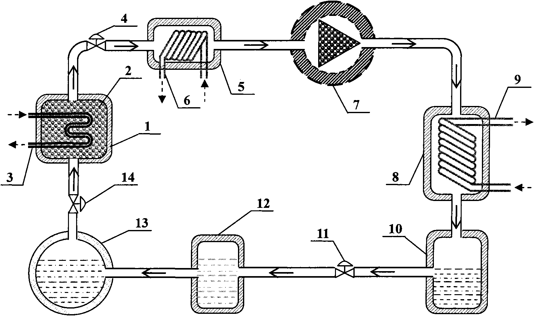
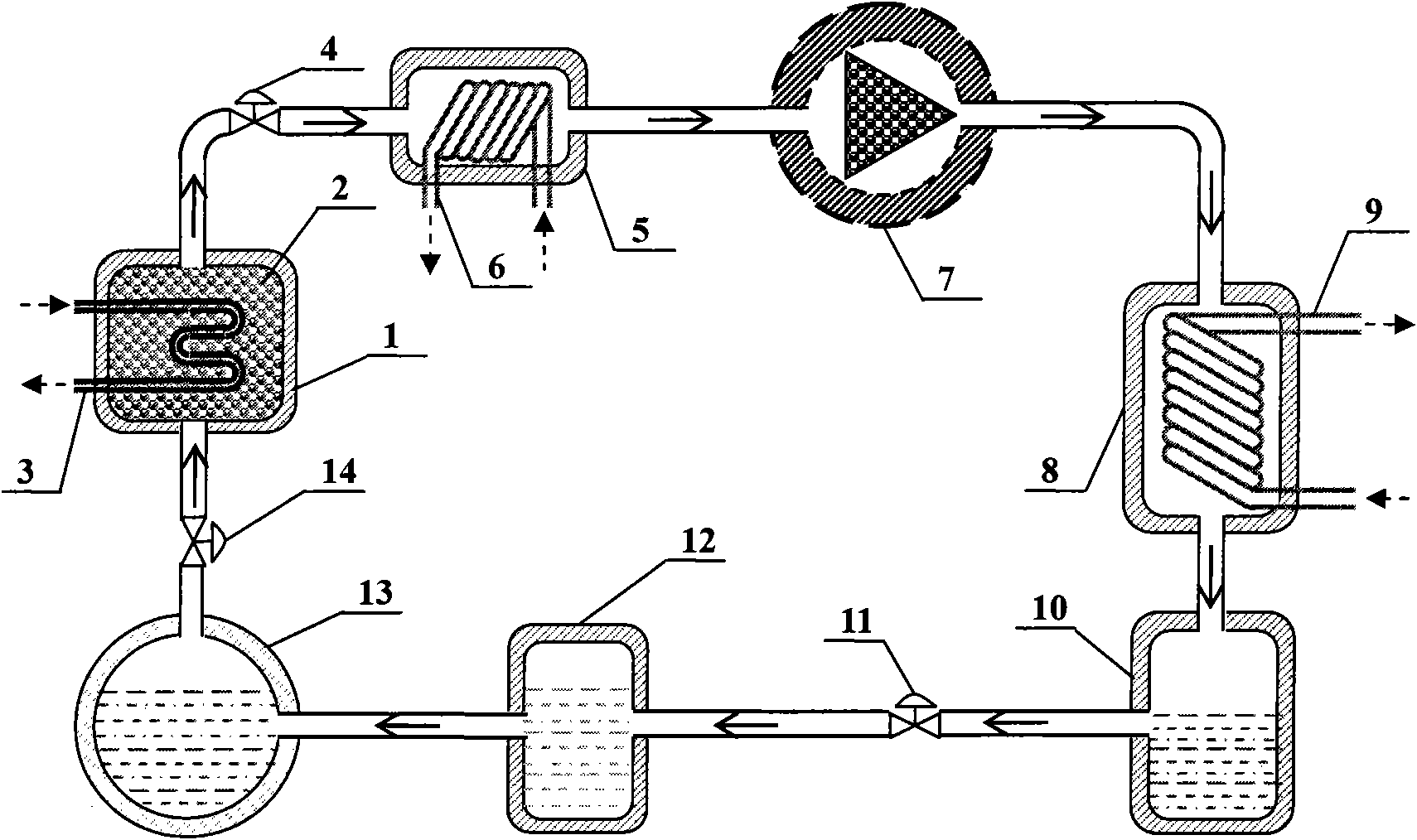
[0023] like figure 1 As shown, this embodiment includes: adsorption bed 1, adsorbent 2, adsorption bed heat exchanger 3, desorption valve 4, cooler 5, cooler heat exchange coil 6, compressor 7, condenser 8, condenser exchange Heat coil 9, high-pressure liquid storage tank 10, throttle valve 11, low-pressure liquid storage tank 12, evaporator 13, adsorption valve 14.

[0024] In this embodiment, an adsorption bed 1 is added between the evaporator and the compressor of the traditional compression refrigeration system, the outlet of the adsorption bed 1 is connected to the inlet of the desorption valve 4, the outlet of the desorption valve 4 is connected to the inlet of the cooler 5, and the outlet of the cooler 5 It is connected with the inlet of compressor 7, the outlet of compressor 7 is connected with the inlet of condenser 8, the outlet of condenser 8 is connected with the inlet of high-pressure liquid storage tank 10, the outlet of high-pressure liquid storage tank 10 is co...

Embodiment 2

[0032] In this embodiment, the number of adsorption beds is 4, and the refrigerant gas passages between different adsorption beds are connected in parallel to achieve the purpose of mass recovery; the heat exchangers of different adsorption beds are connected in series to achieve higher recovery temperature. The heat of adsorption and the purpose of controlling the rate of adsorption of refrigerant.

[0033] In this embodiment, the compressor 7 is an oil-containing screw compressor. In order to prevent the compressor from polluting the adsorbent with lubricating oil, an oil separator is installed at the outlet of the compressor, and an oil filter device is installed between the evaporator and the adsorption bed.

[0034] In this embodiment, during the peak, peak and normal periods when the electricity price is relatively expensive, the four adsorption beds in the system perform the evaporative refrigeration-adsorption process, and the high-pressure and normal-temperature refrig...

Embodiment 3

[0040] In this embodiment, the number of adsorption beds 1 is 10, and the refrigerant gas channels between different adsorption beds are connected in parallel to achieve the purpose of mass recovery; the heat exchangers of different adsorption beds are connected in series to achieve higher recovery. The temperature is the heat of adsorption and the purpose of controlling the rate of adsorbed refrigerant.

[0041] In this embodiment, the compressor 7 is a moving magnet linear compressor.

[0042] In this embodiment, during the peak, peak and normal periods when the electricity price is relatively expensive, the seven adsorption beds in the system perform the evaporative refrigeration-adsorption process, and the high-pressure and normal-temperature refrigerant in the high-pressure liquid storage tank 10 enters the low-pressure liquid storage through the throttle valve 11 The tank 12 then enters the evaporator 13 for evaporation and refrigeration, and is adsorbed by the adsorptio...


PUM


Abstract

The invention belongs to the technical field of refrigeration and cold accumulation, and discloses an absorption-mechanical compression coupling refrigeration and cold accumulation system. The absorption-mechanical compression coupling refrigeration and cold accumulation system comprises an absorption bed, a desorbing valve, a cooler, a compressor, a condenser, a high-pressure liquid-storage tank, a throttling valve, a low-pressure liquid-storage tank, an evaporator and an absorbing valve. An absorption bed heat exchanger is arranged in the absorption bed; an absorbing agent is filled in the absorption bed; the outlet of the absorption bed is connected with the inlet of the desorbing valve; the outlet of the desorbing valve is connected with the inlet of the cooler; the outlet of the cooler is connected with the inlet of the compressor; the outlet of the compressor is connected with the inlet of the condenser; the outlet of the condenser is connected with the inlet of the high-pressure liquid-storage tank; the outlet of the high-pressure liquid-storage tank is connected with the inlet of the throttling valve; the outlet of the throttling valve is connected with an inlet of the low-pressure liquid-storage tank; the outlet of the low-pressure liquid-storage tan is connected with the inlet of the evaporator; the outlet of the evaporator is connected with the inlet of the absorbing valve; and the outlet of the absorbing valve is connected with the inlet of the absorbing bed. With the adoption of the absorption-mechanical compression coupling refrigeration and cold accumulation system, low-grade heat source can be utilized to realize cold accumulation without cold lass, so that the power consumption of the system and the operation cost are obviously reduced.

Description

technical field [0001] The invention belongs to the technical field of refrigeration and cold storage, in particular to an adsorption-mechanical compression coupled refrigeration and cold storage system. Background technique [0002] In order to alleviate the shortage of power supply in our country, improve the utilization efficiency of energy and power resources, reduce the investment cost and operation cost of the power grid, and optimize and adjust the energy structure, my country has implemented a peak-valley time-of-use electricity price system. At present, one of the main ways to reduce the operating cost of refrigeration units is cold storage, but adding cold storage devices faces a series of problems such as high additional investment costs, high cooling capacity loss, large power consumption of circulating pumps, and corrosion of eutectic cool storage agents. Adsorption refrigeration technology has obvious advantages such as environmental friendliness, availability ...

Claims


Application Information

Patent Timeline
Patent Type & Authority Applications(China)
IPC IPC(8): F25B25/02F25B41/00
Inventor 赖艳华董震吕明新
Owner SHANDONG UNIV
Why Eureka
Try Eureka