Brush-less motor using vernier structure

a brushless motor and vernier technology, applied in the field of motors, can solve the problems of poor torque control, low efficiency of current-carrying motors in operation, and insufficient use of motors to achieve the effect of improving the volumetric efficiency of motors, increasing output, and reducing torqu

Inactive Publication Date: 2006-06-20
PANASONIC CORP
View PDF24 Cites 24 Cited by
  • Summary
  • Abstract
  • Description
  • Claims
  • Application Information

AI Technical Summary

Benefits of technology

[0024]Small teeth provided on the edge of each salient pole result in selectively taking magnetic flux of magnetic poles facing the small teeth into the salient pole. Therefore, increasing a number of small teeth instead of increasing a number of salient poles restrains a number of effective magnetic fluxes from decreasing, and a number of magnetic poles can be increased arbitrarily, which improves the volumetric efficiency of the motor. As a result, a motor can be downsized maintaining the same characteristics, or a motor can increase its output maintaining the same size.

Problems solved by technology

As a result, the motor cannot use fully enough the improved performance of the magnet, so that the motor per se improves its performance only to some extent.
This prior art is thus not optimized for an output density representing an output per unit volume, or volumetric efficiency representing how much a motor can be downsized maintaining its characteristics, so that this prior art, as it is, cannot apply to brush-less motor.
Therefore, in general, the current-carrying method of the stepping motor has lower efficiency than that of the brush-less motor in operation.
What is more, the stepping motor is good at positioning control but is poor at torque control.

Method used


Image

  • Brush-less motor using vernier structure
  • Brush-less motor using vernier structure
  • Brush-less motor using vernier structure

Examples


exemplary embodiment 1

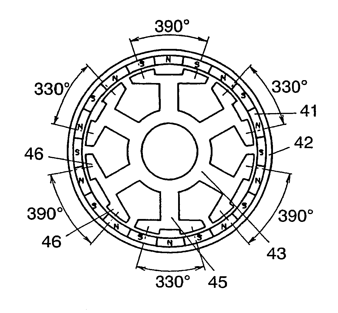
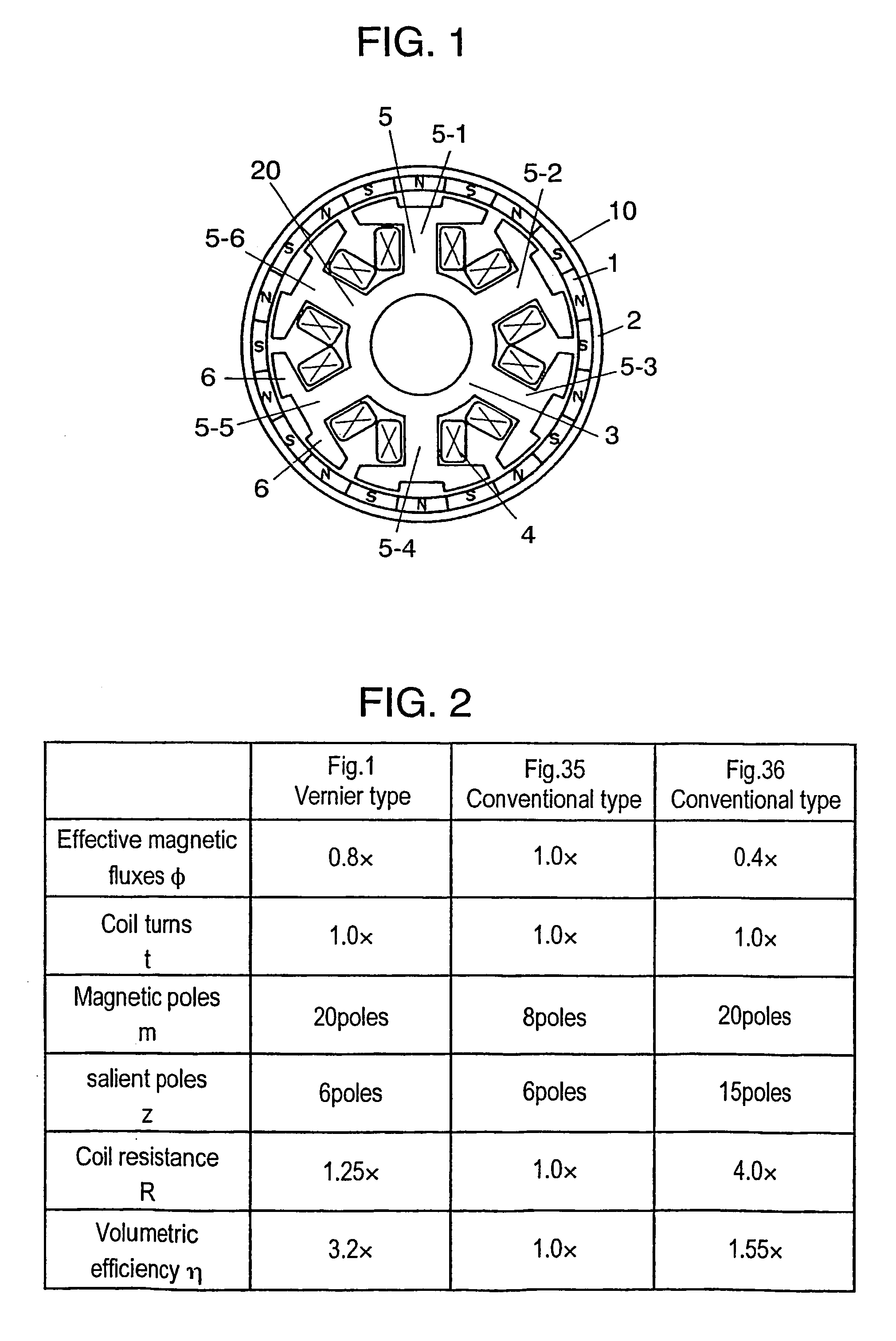
[0081]FIG. 1 is a schematic view illustrating a structure of a magnetic circuit of a brush-less motor in accordance with the first embodiment of the present invention. In FIG. 1, cylindrical magnet 1 is magnetized N and S poles alternately and uniformly at its inner wall to form 20 poles in total. Back yoke 2 is fixed to an outer wall of magnet 1. Core 3 is made of silicon steel plates that has been punched by press and laminated axially. Core 3 includes six salient poles 5 (poles 5-1 through 5-6) equi-spaced from each other. Coils 4 are wound on each salient pole 5. Each salient pole 5 is toothed and has two small teeth 6 at its edges facing magnet 1, so that 12 small teeth 6 in total are formed with a pitch which corresponds to two poles (N and S poles, i.e., 360 degrees in electrical angles) of magnet 1.

[0082]An innovative feature of this first embodiment is the two small teeth provided to an edge of each salient pole with a pitch corresponding to two poles of the magnet. These s...

exemplary embodiment 2

[0135]FIG. 11 shows magnetizing distribution of a magnet of a brush-less motor in accordance with the second exemplary embodiment of the present invention. Other magnetic circuit structures of the brush-less motor used in the second embodiment stay the same as those of the first embodiment shown in FIG. 1. In FIG. 11, magnet 21 is magnetized in predetermined skewed angle θ so that pole positions are different at an upper end and a lower end, where angle θ is a mechanical angle viewed from the rotation center and called a central angle.

[0136]In the case of a brush-less motor having a vernier-structure, “p”=a number of magnetic poles of the magnet, “z”=a number of salient poles of the core, then a waveform of cogging torque repeats “k” times per rotation, where “k” is the least common multiple of “p” and “z”.

[0137]Skew-magnetization of the magnet averages the waveforms of cogging toque in a laminated direction, so that an absolute value of the cogging torque becomes smaller.

[0138]FIG....

exemplary embodiment 3

[0146]In the second embodiment discussed above, a skew-angle is used in magnetizing. In this third embodiment, a shape of a core is devised so that cogging torque can be reduced. FIG. 13 illustrates a core shape of a brush-less motor in accordance with the third embodiment. The brush-less motor differs from that of the first embodiment in the following point: In FIG. 13, a shape of core 33 has different open angle α at small teeth 36 on an edge of salient pole 35 from that of the first embodiment shown in FIG. 1. The other structures stay the same as those in the first embodiment.

[0147]A change in open angle α at the small teeth greatly changes cogging torque. FIG. 14 show a waveform of cogging torque depending on a change in open angle α at the small teeth. FIG. 14A shows a waveform at open angle α=120 degrees in electrical angles, FIG. 14B shows at 150 degrees, and FIG. 14C shows at 180 degrees.

[0148]As shown in FIG. 14A, the cogging torque repeats the waveform six times during ro...


PUM


Abstract

A brush-less motor includes a rotor with a magnet alternately magnetized N pole and S pole in a rotating direction, and a core with plural salient poles on which coils are wound. The core faces the magnet to form a magnetic circuit. Each one of the salient poles are toothed and provided with small teeth at an edge facing the magnet. The small teeth have a pitch corresponding to two poles of the magnet. Powering to the coil responsive to a rotor position drives the rotor. This structure substantially increases volumetric efficiency of the motor.

Description

[0001]This application is a U.S. national phase application of PCT international application PCT / JP02 / 07954.TECHNICAL FIELD[0002]The present invention relates to a motor to be used as a driving source of an apparatus, more particularly it relates to a brush-less motor of which stator employs a vernier structure.BACKGROUND ART[0003]Motors are employed as a driving source of various apparatuses such as video and audio apparatuses, office automation apparatuses, home appliances, transporting devices, factory automation devices. These apparatuses and devices have been equipped with more functions year by year, thus a number of motors employed in these apparatuses and devices has increased accordingly. At the same time, the apparatuses and devices have been downsized and done their jobs at a higher speed. The market therefore has requested that motors output a greater power with a smaller body.[0004]Various types of motors are used, such as an induction motor, a dc motor with a brush, a ...

Claims


Application Information

Patent Timeline
Patent Type & Authority Patents(United States)
IPC IPC(8): H02K1/12H02K1/00H02K21/12H02K37/14H02K1/14H02K1/16H02K1/27H02K21/22H02K29/00H02K29/03H02K37/12
CPCH02K1/146H02K21/222H02K37/12H02K29/03H02K37/14
Inventor FUJINAKA, HIROYASU
Owner PANASONIC CORP
Why Eureka
Try Eureka