Variable displacement dual vane pump

A displacement pump and vane pump technology, applied in the field of sliding vane pumps, can solve problems such as pollution, torque loss, and affecting reliability

Inactive Publication Date: 2009-12-16
SLW AUTOMOTIVE
View PDF0 Cites 27 Cited by
  • Summary
  • Abstract
  • Description
  • Claims
  • Application Information

AI Technical Summary

Problems solved by technology

This can cause a significant amount of torque loss
Another problem can be contamination within the pump which can affect reliability

Method used


Image

  • Variable displacement dual vane pump
  • Variable displacement dual vane pump
  • Variable displacement dual vane pump

Examples


Embodiment Construction

[0020] The following description of one or more preferred embodiments is merely exemplary in nature and is in no way intended to limit the present invention, its application, or uses.

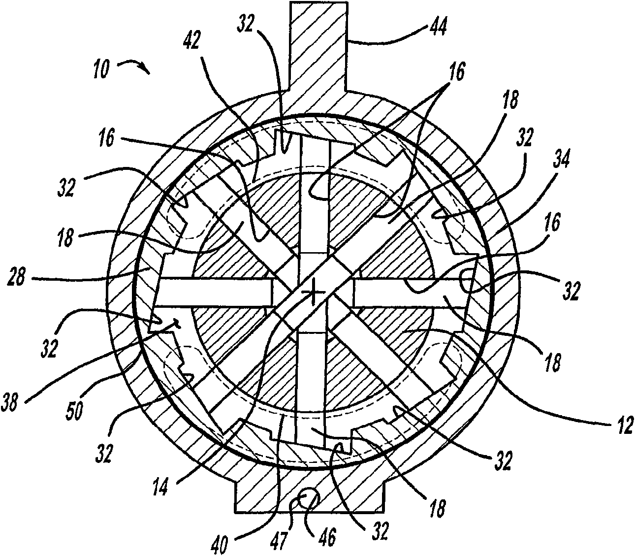
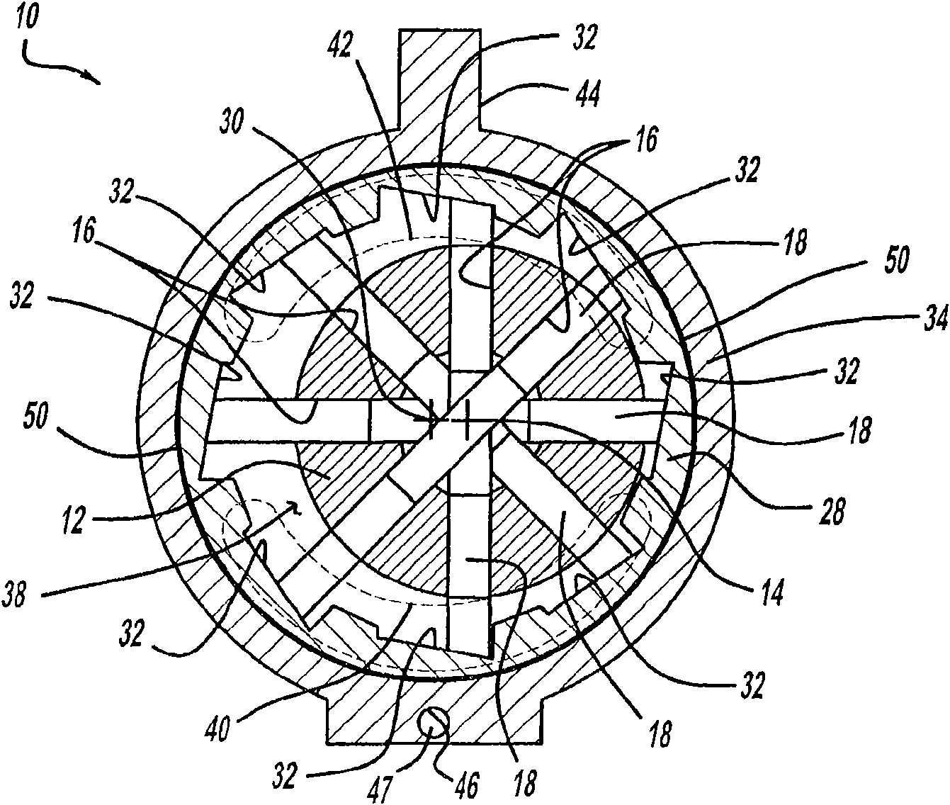
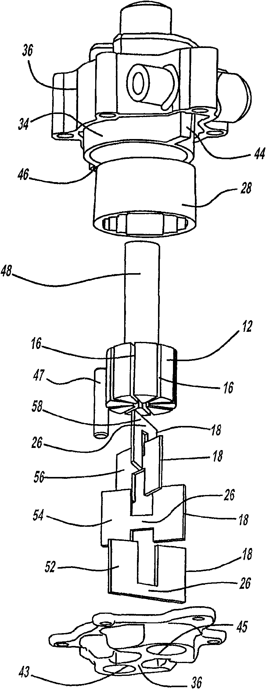
[0021] Referring generally to these drawings, a sliding vane pump according to the present invention is generally indicated by 10. The pump 10 has an inner rotor 12 that rotates about a first axis 14. The inner rotor 12 also has a series of slits 16 for receiving a plurality of blades 18. The blades 18 have a first side 20 which is offset from and parallel to a second side 22. The blades 18 also have a third side 21 which is parallel to a fourth side 23 and is equal in length compared to it. Both the third side 21 and the fourth side 23 serve as a flat joint surface 24. The blade 18 also includes an extension 26 which has a reduced width compared to the rest of the blade 18. The pump 10 also has an outer rotor 28 that rotates about a second axis 30 and has recesses 32 for receiving the flat joint s...


PUM


Abstract

The present invention is a variable displacement pump having an inner rotor rotatable about a first axis and having at least two slots. The pump also has at least two vanes, each located in a distinct one of the at least two slots. The pump also has an outer rotor rotatable about a second axis, operably associated with the inner rotor, the outer rotor having two or more recesses, each configured to receive one of the vanes. The pump also includes an expandable chamber formed by the outer rotor and the inner rotor, an eccentric ring surrounding the outer rotor, and a housing. The eccentric ring is located within the housing for adjusting the relative relationship between the first axis and the second axis in order to vary the displacement of the pump.

Description

[0001] Cross references to related applications [0002] This application is a PCT international application with U.S. Provisional Application No. 60 / 922,683 filed on April 10, 2007. The disclosure of the above application is incorporated herein by reference. Technical field [0003] The present invention relates to a sliding vane pump; more specifically, the present invention relates to a sliding vane pump having a stacked, integrated vane configuration. Background technique [0004] Sliding vane pumps are usually used to transport fluid from an input port to an output port. Typically, they have an eccentric ring, and an inner rotor, which is typically fixed to a shaft and rotates with it; and a series of blades that slide in and out of a set of blade gaps . When these blades rotate with the inner rotor, the blades will slide along the inner surface of the eccentric ring. The eccentricity between the inner rotor and the eccentric ring can be changed to change the amount of fluid ...

Claims


Application Information

Patent Timeline
Patent Type & Authority Applications(China)
IPC IPC(8): F04C2/344F04C18/344
CPCF04C14/226F04C2/348
Inventor C·郭
Owner SLW AUTOMOTIVE
Why Eureka
Try Eureka