Photosensitive drum for printer cartridge and method for mounting the same

a printer cartridge and photosensitive technology, applied in the direction of instruments, electrographic process equipment, corona discharge, etc., can solve the problems of deformation of the cartridge shape, difficulty in replacing the photosensitive drum b>10, and inability to properly work the recycled cartridg

Inactive Publication Date: 2007-10-11
PARK&OPC
View PDF2 Cites 118 Cited by
  • Summary
  • Abstract
  • Description
  • Claims
  • Application Information

AI Technical Summary

Benefits of technology

[0005]Therefore, it is an object of the present invention to provide a photosensitive drum for a printer

Problems solved by technology

However, in some printers, for example Hewlett-Packard's HP2600 printer, the drum connectors 32a, 32b are permanently fixed on the cartridge frame 30, for example, with an adhesive, which makes it difficult to replace the photosensitive drum 10.
If the

Method used


Image

  • Photosensitive drum for printer cartridge and method for mounting the same
  • Photosensitive drum for printer cartridge and method for mounting the same
  • Photosensitive drum for printer cartridge and method for mounting the same

Examples


Embodiment Construction

[0014]A more complete appreciation of the invention, and many of the attendant advantages thereof, will be better appreciated by reference to the following detailed description in conjunction with accompanying drawings.

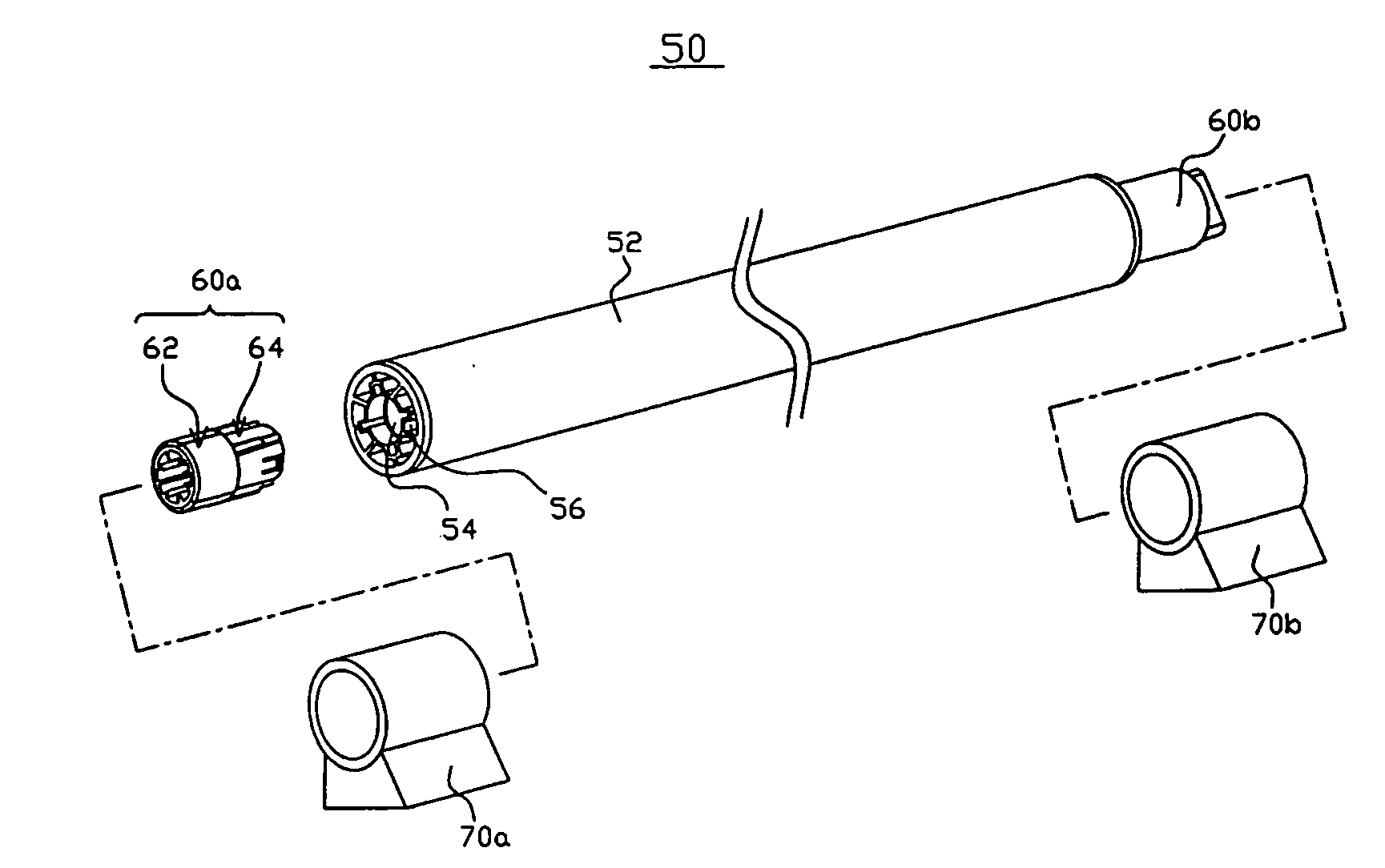
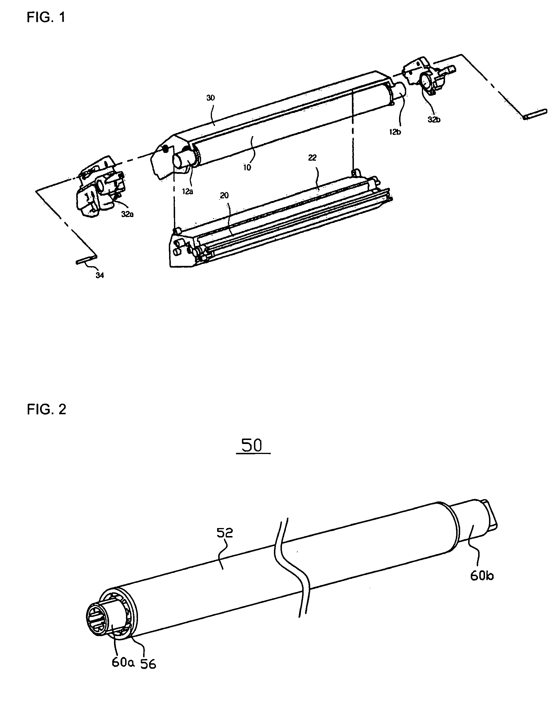
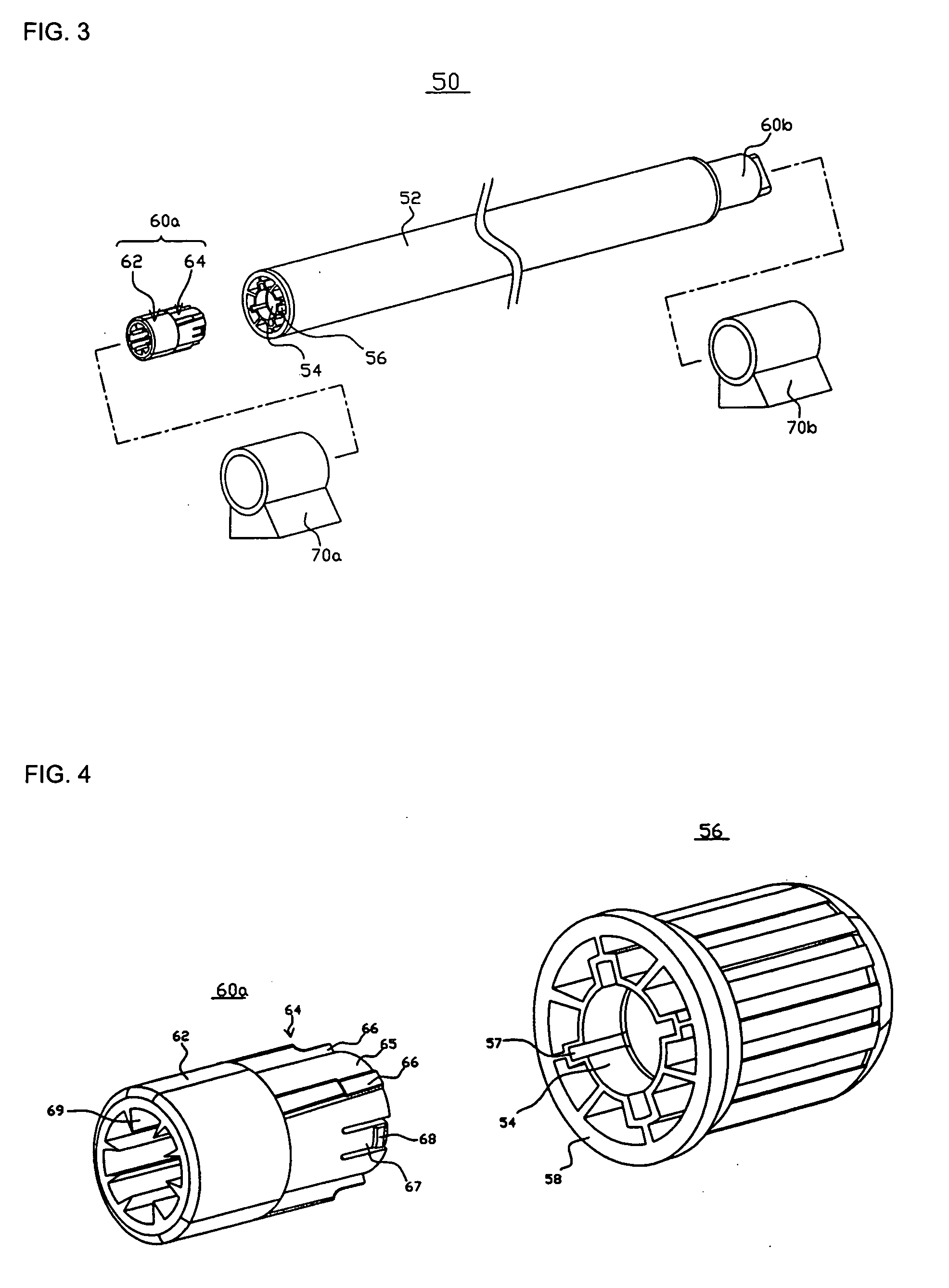
[0015]FIG. 2 is a perspective view of a photosensitive drum according to an embodiment of the present invention, and FIG. 3 is an exploded perspective view for showing the mounting process of the photosensitive drum according to an embodiment of the present invention. As shown in FIG. 2 and FIG. 3, the photosensitive drum 50 according an embodiment of the present invention comprises a cylindrical drum 52 having a photosensitive layer on the cylindrical surface thereof, and a pair of rotation shafts 60a, 60b which is respectively mounted on the sides of the cylindrical drum 52 for rotating and supporting the cylindrical drum 52 wherein at least one of the rotation shafts 60a, 60b is insert-fitted to the side of the cylindrical drum 52. The cylindrical drum 52 can be a ...


PUM


Abstract

A photosensitive drum for a printer cartridge, which can be easily mounted on a printer cartridge of which the positions of drum connectors are fixed, is disclosed. The photosensitive drum for a printer cartridge comprises a cylindrical drum having a photosensitive layer on a cylindrical surface thereof; and a pair of rotation shafts which is respectively mounted on the sides of the cylindrical drum for rotating and supporting the cylindrical drum, wherein at least one of the rotation shafts is insert-fitted to the side of the cylindrical drum.

Description

FIELD OF THE INVENTION[0001]This invention relates to a photosensitive drum for a printer cartridge, and more specifically to a photosensitive drum for a printer cartridge, which can be easily mounted on the printer cartridge of which the positions of drum connectors are fixed, and a method for mounting the photosensitive drum on the printer cartridge.BACKGROUNDS OF THE INVENTION[0002]An electrophotographic image forming device is an apparatus for forming an image on a recording medium by an electrophotographic process. Examples of the image forming device include a copy machine, a printer, and so on, and the examples of the recording medium includes a paper, an OHP (Over head projector) film, and so on. The electrophotographic image forming process includes the steps of (1) forming a statically charged image or an electro-conductive image (generally, “latent image”), which corresponds to a recording image, on the surface of a photosensitive drum, for example OPC (Organic photocondu...

Claims


Application Information

Patent Timeline
IPC IPC(8): G03G15/00
CPCG03G15/751F16D1/10G03G15/04G03G15/348G03G2217/0075
Inventor CHO, MYUNG-LAEHAN, MICHAELKIM, HAN-SHIKCHO, SEONG-JINJEON, JUN-HO
Owner PARK&OPC
Why Eureka
Try Eureka