
Placement rack convenient to lift

A technology for placing racks and supporting racks is applied in the field of placing racks, which can solve the problems of inconvenient use and messy placement of tools, and achieve the effects of simple structure, convenient and beautiful use, and reasonable design.

Inactive Publication Date: 2016-03-16
QINGDAO TECHCAL UNIV QINDAO COLLEGE
View PDF0 Cites 0 Cited by
  • Summary
  • Abstract
  • Description
  • Claims
  • Application Information

AI Technical Summary

Problems solved by technology

In general, the tools in the factory are very messy and inconvenient to use

Method used


Image

  • Placement rack convenient to lift

Examples


Embodiment Construction

[0009] The present invention will be further described below in conjunction with accompanying drawing:

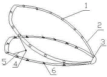
[0010] As shown in the figure, a shelf that is easy to lift and place is mainly composed of a support hole 1, a movable support frame 2, a connecting body 3, a fixed body 4, a support rod 5, and an elastic clip 6. It is characterized in that: the support The hole 1 is connected with the movable supporting frame 2, the movable supporting frame 2 is connected with the connecting body 3, the fixed body 4 is connected with the supporting rod 5, and the supporting rod 5 is connected with the movable The support frame 2 is connected, and the elastic clip 6 is connected with the movable support frame 2 .

[0011] The function of the support hole 1 is to place various tools. When in use, the movable support frame 2 is opened by the action of the fixed body 4 and the support rod 5, which is convenient for taking and placing tools. When not in use, the movable support frame 2 is clos...


PUM


Abstract

The invention relates to a placement rack convenient to lift. The placement rack convenient to lift is mainly composed of supporting holes, a movable support, a connector, a fixing member, supporting rods and elastic clamps. The placement rack convenient to lift has the characteristics of being reasonable in design, simple in structure, convenient to use, attractive in appearance and capable of simultaneously placing multiple tools of different models.

Description

technical field [0001] The invention relates to a placement rack, in particular, a placement rack that is convenient for lifting and placing is designed. Background technique [0002] Tools originally refer to the utensils needed for work, and later extended to the means to achieve, complete or promote a certain thing. Tool is a relative concept, because its concept is not a specific substance, so as long as the substance that can change the substance is a tool relative to the substance that can be changed by it. In general, the tools in the factory are very messy and inconvenient to use. Contents of the invention [0003] In order to solve the above problems, the object of the present invention is to provide an easy-to-handle and easy-to-use placing rack. [0004] In order to achieve the above-mentioned purpose, the present invention is an easy-to-lift placement rack, which is mainly composed of a support hole, a movable support frame, a connecting body, a fixed body, a...

Claims


Application Information

Patent Timeline
Patent Type & Authority Applications(China)
IPC IPC(8): B25H3/04
CPCB25H3/04
Inventor 王建平
Owner QINGDAO TECHCAL UNIV QINDAO COLLEGE
Learn More