Constant Force Mechanisms, Movements and Clocks

A movement and power source technology, used in clocks, clock driving mechanisms, mechanically driven clocks, etc., can solve problems such as the inability to ensure deflection, the reduction of timing accuracy, and the large variation of deflection torque. Timing accuracy, stable drive, ensuring the effect of timing accuracy

Active Publication Date: 2019-04-09
SEIKO INSTR INC
View PDF5 Cites 0 Cited by
  • Summary
  • Abstract
  • Description
  • Claims
  • Application Information

AI Technical Summary

Problems solved by technology

[0006] However, in the prior art, since the spring for torque adjustment is formed of a leaf spring, a sufficient amount of deflection cannot be ensured, and the change in torque per unit amount of deflection becomes large.
Therefore, there is a concern that when the constant force mechanism operates, the torque fluctuation rate due to the change in the urging force of the torque adjustment spring increases, and the timing accuracy decreases.

Method used


Image

  • Constant Force Mechanisms, Movements and Clocks
  • Constant Force Mechanisms, Movements and Clocks
  • Constant Force Mechanisms, Movements and Clocks

Examples


Embodiment Construction

[0032] Hereinafter, embodiments of the present invention will be described with reference to the drawings.

[0033] Generally, a mechanical body including a driving part of a timepiece is called a "movement". The state in which the dial and hands are attached to the movement and put into the watch case to form a finished product is called "complete" of the watch. Of the two sides of the bottom plate constituting the base plate of the timepiece, the side where the glass of the timepiece case is located, that is, the side where the dial is located is referred to as the “back side” of the movement. In addition, the side where the case back cover of the timepiece case exists among both sides of the base plate, that is, the side opposite to the dial is referred to as the "front side" of the movement.

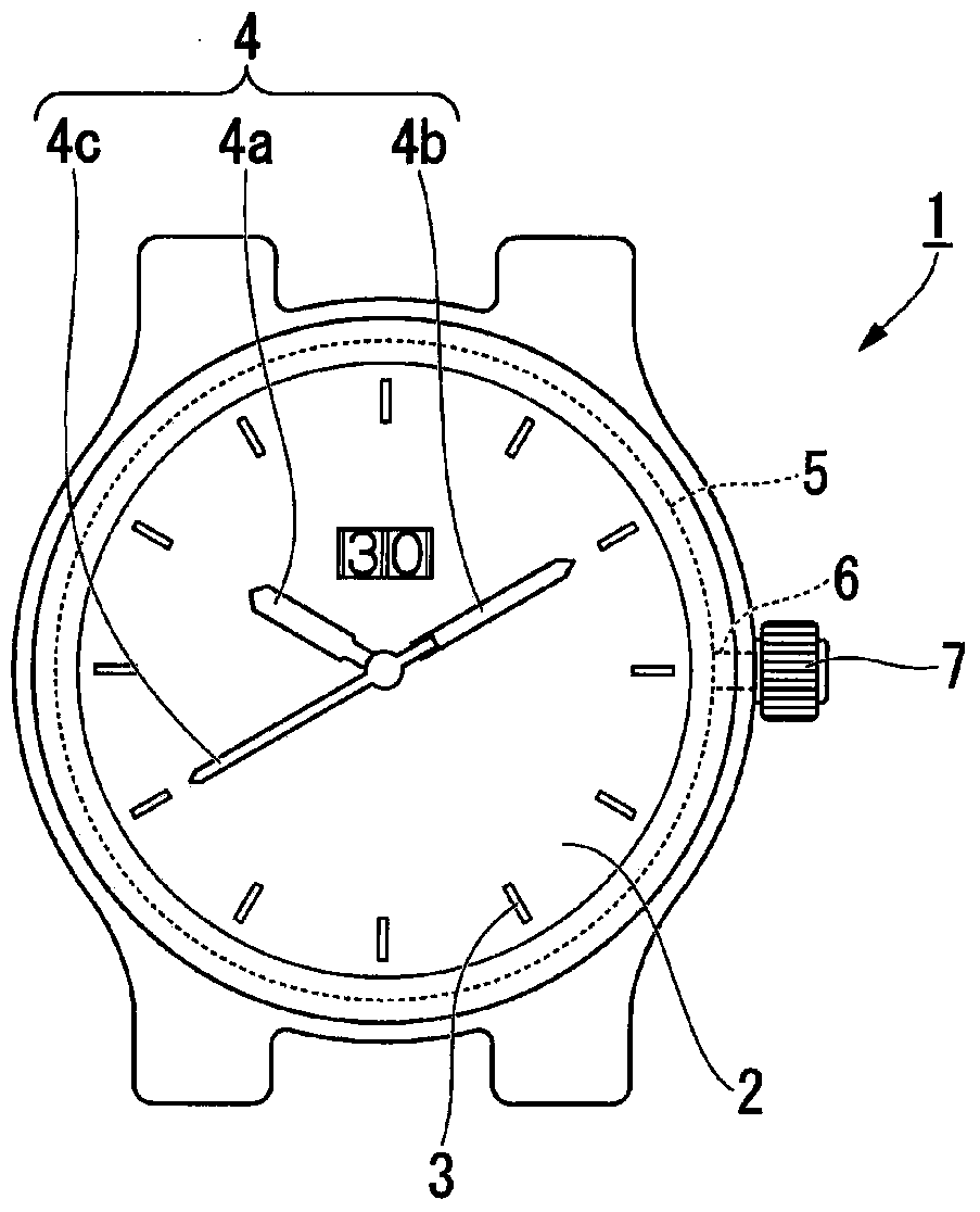
[0034] figure 1 It is a top view of the clock 1.

[0035] like figure 1 As shown, the timepiece 1 is provided with a dial 2 including a scale 3 etc., the scale 3 indicating infor...


PUM


Abstract

The present invention provides a constant force mechanism, a movement, and a timepiece, which can sufficiently ensure the amount of deflection of a spring for torque adjustment, and can ensure good timing accuracy. The constant force mechanism has: a power switching part (11), which is assembled in the wheel train (70) from the barrel as a power source to the escapement (60); a swing lever (20), which switches the power switching part (11) supported to be rotatable around the first shaft (C1); and a cycle control mechanism (30) having: a stopper wheel (31) rotatable by being transmitted power (action torque) from the barrel; torque The adjustment spring (40) drives the escapement (60) by means of expansion and contraction; and the locking part (39), which operates through the torque adjustment spring (40) and locks with the stop wheel (31) , the cycle control mechanism (30) makes the swing lever (20) rotate intermittently.

Description

technical field [0001] The invention relates to a constant force mechanism, a movement and a clock. Background technique [0002] In a mechanical timepiece, when the torque transmitted from the barrel as the power source to the escapement fluctuates in accordance with the unwinding (卷き解け) of the mainspring of the barrel, the swing angle of the balance with hairspring changes and the timepiece The speed of the changes. Therefore, in order to suppress fluctuations in the torque transmitted to the escapement, a constant force mechanism has been proposed in which a spring for torque adjustment is disposed between the barrel and the escapement. [0003] For example, the constant force mechanism described in Patent Document 1 includes: a fixed wheel; a carriage arm that rotates around the axis of the fixed wheel; and a torque adjustment spring connected to the carrier arm via a link mechanism. The constant force mechanism described in Patent Document 1 uses a long leaf spring as...

Claims


Application Information

Patent Timeline
Patent Type & Authority Patents(China)
IPC IPC(8): G04B1/22G04B17/28
CPCG04B1/225
Inventor 藤枝久
Owner SEIKO INSTR INC
Why Eureka
Try Eureka