Particle conveying mechanism

A conveying mechanism and particle technology, which is applied in the direction of conveyors, conveying bulk materials, transportation and packaging, etc., can solve the problems of limited conveying height, high noise, and non-adjustable conveying pressure, so as to reduce noise emission, high conveying height, and realize The effect of automation

Inactive Publication Date: 2016-03-30
南京法宁格节能科技股份有限公司
View PDF4 Cites 2 Cited by
  • Summary
  • Abstract
  • Description
  • Claims
  • Application Information

AI Technical Summary

Problems solved by technology

[0002] At present, the transportation methods of plastic particles generally adopt two methods: centrifugal fan with text type three-way transportation and vortex centrifugal fan transportation. The first method is noisy, the conveying height is limited, the conveying pressure cannot be adjusted, and it cannot be used for fragile products; The second method is expensive, high cost, limited conveying height, slow conveying speed, non-adjustable conveying pressure, and cannot be used for fragile products

Method used


Image

  • Particle conveying mechanism

Examples


Embodiment Construction

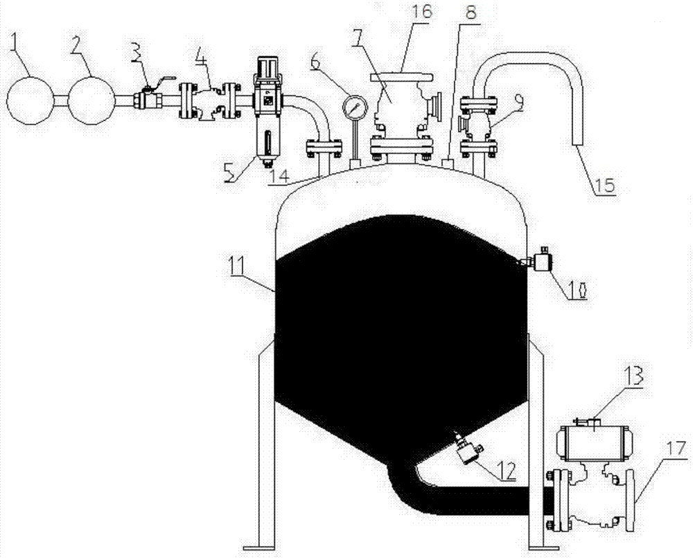
[0014] Such as figure 1 As shown, a particle conveying mechanism according to the present invention includes a storage tank 11, above which is provided an air source assembly, a pressure gauge 6, a feed valve 7, a pressure switch 8 and an exhaust valve 9. The air source assembly includes an air compressor 1, an air storage tank 2, a manual valve 3, an air inlet valve 4, and a pressure regulating valve 5 which are connected in sequence. One end of the pressure regulating valve 5 is connected to the storage tank 11. The side of the storage tank 11 is provided with a first material level sensing switch 10, and the bottom of the storage tank 11 is provided with a second material level sensing switch 12 and a discharge valve 13; the feed valve 7, the exhaust valve 9, and the discharge valve The material valve 13 and the storage tank 11 are all connected by a flange, and the pressure switch 8, the first material level sensor switch 10, the second material level sensor switch 12 and t...


PUM


Abstract

The invention relates to the solid-phase material conveying technology, in particular to a particle conveying mechanism. The particle conveying mechanism comprises a storage tank. An air source assembly, a pressure gage, a feed valve, a pressure switch and an exhaust valve are arranged above the storage tank. The air source assembly comprises an air compressor, an air storage tank, a hand valve, an inlet valve and a pressure regulating valve, all of which are connected in sequence. One end of the pressure regulating valve is connected with the storage tank. A first material level induction switch is arranged on the side face of the storage tank. A second material level induction switch and a discharge valve are arranged at the bottom of the storage tank. The particle conveying mechanism is larger in conveying height, the requirement for a special plant structure can be better met, meanwhile, noise discharge is reduced, the impact generated on products is small, and conveying of diverse products can be better achieved; and material conveying can be finished within short time, the conveying amount is large, manual operation is not needed in the whole conveying process, and automation can be completely achieved.

Description

Technical field [0001] The invention relates to a technology for conveying solid phase materials, in particular to a particle conveying mechanism. Background technique [0002] At present, the conveying method of plastic particles generally adopts two methods of centrifugal fan with three-way conveying and vortex centrifugal fan. The first method is noisy, the conveying height is limited, the conveying pressure cannot be adjusted, and it cannot be used for easily broken products; The second method is expensive, high cost, limited conveying height, slow conveying speed, unadjustable conveying pressure, and cannot be used for easily broken products. Summary of the invention [0003] The purpose of the present invention is to overcome the shortcomings of the prior art and provide a particle conveying mechanism with a higher conveying height, which can better meet the needs of special plant structures, while reducing noise emissions and having less impact on products, thereby making i...

Claims


Application Information

Patent Timeline
Patent Type & Authority Applications(China)
IPC IPC(8): B65G53/16B65G53/34
CPCB65G53/16B65G53/34B65G2201/042
Inventor 郭鑫齐刘铜杜小刚
Owner 南京法宁格节能科技股份有限公司
Why Eureka
Try Eureka