Continuous casting roller and assembling method thereof

A technology of continuous casting rolls and roll sleeves, applied in the field of continuous casting rolls and their assembly, can solve the problem of scrapping of mandrels and bearing assemblies, lip seals stuck in spiral grooves and/or undercut grooves, and complicated assembly. and other problems, to achieve the effect of reducing thermal fatigue load, easy interchange and maintenance, and reliable sealing performance

Active Publication Date: 2021-10-29
CHANGZHOU BAOLING HEAVY IND MACHINERY
View PDF9 Cites 3 Cited by
  • Summary
  • Abstract
  • Description
  • Claims
  • Application Information

AI Technical Summary

Problems solved by technology

Therefore, the product has the disadvantage that assembly is cumbersome and difficult
[0005] 2. When assembling the mandrel and the bearing assembly, because the spiral groove on the mandrel will cut the seal in the bearing assembly, a spacer with a special structure is specially made to solve this problem. Only through the isolation of the spacer can it be smoothly The bearing assembly is assembled accurately, and the bearing assembly is installed through the spacer, which increases the cost and process, and makes the assembly cumbersome
[0006] Third, the shaft shoulder in the middle of the mandrel is used to install the bearing assembly, and the parts on both sides of the shaft shoulder on the mandrel are used for interference fit with the roller sleeve. When the bearing assembly is damaged and needs to be disassembled, the two sides of the bearing assembly There are spiral grooves and relief grooves on the peripheral surface of the mandrel. No matter which end of the mandrel the bearing assembly moves to, it will pass through the spiral grooves. In the event that the lip seal within the assembly pops into the helical groove and / or undercut, causing the lip seal to seize in the helical groove and / or undercut, the housing assembly will not be able to be removed from the mandrel back out, resulting in disassembly failure and scrapping of the mandrel and bearing assembly
[0007] It can be seen that the continuous casting rolls in the prior art have the disadvantages of installation and disassembly due to structural defects.

Method used


Image

  • Continuous casting roller and assembling method thereof
  • Continuous casting roller and assembling method thereof
  • Continuous casting roller and assembling method thereof

Examples


Embodiment Construction

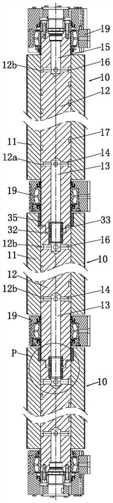
[0037] Such as figure 1 The continuous casting roll shown includes at least two splicing assemblies 10. This embodiment is formed by splicing three splicing assemblies 10. Each splicing assembly 10 includes a roll sleeve 11, a mandrel 12, and a bearing assembly 19. For each Parts and the relationship between the parts are described in detail:

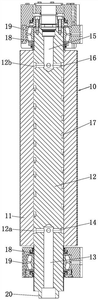
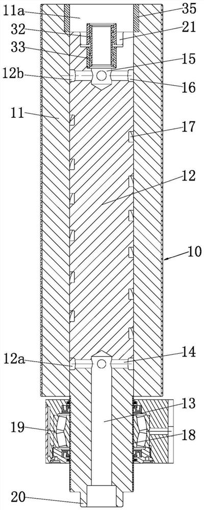
[0038] Such as Figure 1 to Figure 3 , The roller sleeve 11 is a conventional structure, the outer peripheral surface of the roller sleeve 11 is formed by surfacing welding, and can be repaired by surfacing welding after wear and tear, so as to facilitate repeated use.

[0039] Such as Figure 1 to Figure 3 One end of the mandrel 12 is provided with a first axial blind hole 13 and a first radial hole 14 matched with the first axial blind hole 13, and the other end of the mandrel 12 is provided with a second axial blind hole 15 and a The second radial hole 16 matched with the second axial blind hole 15, the outer peripheral surface of...


PUM


Abstract

The invention relates to a continuous casting roller. The continuous casting roller comprises at least two splicing assemblies, and each splicing assembly comprises a roller sleeve, and a core shaft; after the roller sleeves and the core shafts are in interference fit, a first radial hole, a second radial hole and a cooling medium flowing groove in the same core shaft are covered with the same roller sleeve to form a cooling channel, the part, located between the corresponding roller sleeve and the axial end face of the corresponding core shaft, of the corresponding core shaft forms an installation part, when two adjacent splicing assemblies are spliced, the first axial blind hole in the core shaft of one splicing assembly is matched with a second axial blind hole in the core shaft of the other splicing assembly; and the bearing assemblies are arranged on the installation parts in a sleeving mode and is fixed with the installation parts. The C]continuous casting roller has the advantage of being easy to mount and dismount.

Description

technical field [0001] The invention relates to a continuous casting roll and an assembly method thereof. Background technique [0002] The continuous casting roll is the part that conveys the strip steel in the process of producing strip steel. The continuous casting roll is usually composed of a mandrel, a roller sleeve and a bearing. , the second segmented roller and the mandrel, the mandrel runs through the first segmented roller and the second segmented roller, and a rotary joint and a transmission coupling are respectively installed at both ends of the mandrel, between the first segmented roller and the second segmented roller There is an intermediate bearing seat between the second segmented rollers, and the intermediate bearing seat is installed on the mandrel through bearings. At both ends of the mandrel, a left support bearing seat and a right support bearing seat are provided through bearings. There are through cooling water holes, and water pipes are inserted in...

Claims


Application Information

Patent Timeline
Patent Type & Authority Applications(China)
IPC IPC(8): B22D11/06
CPCB22D11/0651
Inventor 杭小庆陈国光罗华兵
Owner CHANGZHOU BAOLING HEAVY IND MACHINERY
Why Eureka
Try Eureka