An Inflow Shaft for Reducing the Air Explosion Intensity of Urban Deep Drainage System

A drainage system and shaft technology, applied in waterway systems, drainage structures, water supply devices, etc., can solve the problem of air explosions that are difficult to meet the inflow capacity of rain and sewage during rainstorms, incorrect positions of air circulation channels, and any protective measures for trapping air masses. and other problems, to achieve the effect of improving gas explosion phenomenon, safe and stable operation, and alleviating intermittent severe surges

Active Publication Date: 2020-05-05
HOHAI UNIV
View PDF7 Cites 2 Cited by
  • Summary
  • Abstract
  • Description
  • Claims
  • Application Information

AI Technical Summary

Problems solved by technology

In the ordinary shaft structure, the shaft is a common circulation channel for water flow and air. Although this design structure has a large inflow area of ​​rainwater and sewage, it does not have any protective measures for the trapped air mass, which will easily lead to the occurrence of gas explosion and surge phenomenon. At the same time, it has been studied by foreign scholars It is found that the air bubbles in the tunnel are not only caused by the inflow of rainwater and sewage, but also can be generated by other means, such as the diameter of the air circulation channel is small, the position of the air circulation channel is incorrect, the water-air interface collapses, etc., so ordinary shafts are prone to gas explosions Phenomenon
[0005] In view of the inflow shaft structure in the existing technology, it is difficult to meet the inflow capacity of rain and sewage during the rainstorm period and improve the gas explosion phenomenon at the same time.

Method used


Image

  • An Inflow Shaft for Reducing the Air Explosion Intensity of Urban Deep Drainage System
  • An Inflow Shaft for Reducing the Air Explosion Intensity of Urban Deep Drainage System
  • An Inflow Shaft for Reducing the Air Explosion Intensity of Urban Deep Drainage System

Examples


Embodiment

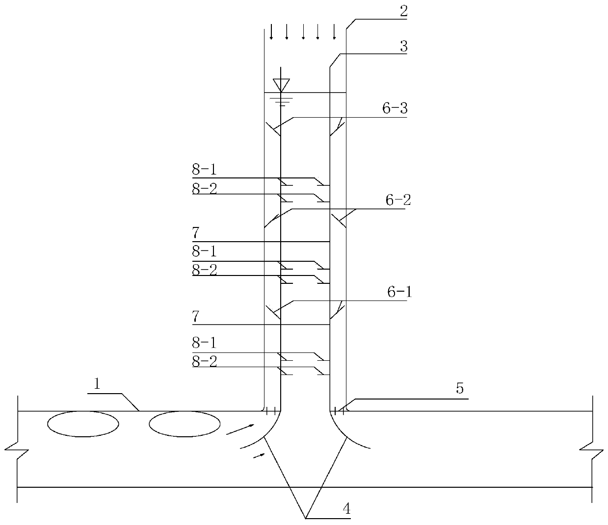
[0040] The drainage pipe inflow shaft device used to improve the gas explosion phenomenon in this embodiment is as follows: figure 2 As shown, a cylinder 3 is arranged on the upper part of the inflow shaft 2 of the deep tunnel 1 . A supporting ring 5 is sleeved between the shaft 2 and the cylinder 3 for fixing the cylinder 3 . The bottom end of the cylinder 3 is provided with an annular bell mouth 4, which guides the trapped air mass into the interlayer between the inflow shaft 2 and the cylinder 3, and plays the role of gas collection. The air hole rings 6-1 to 6-3 are arranged in the interlayer to fully divide the air cavity into air bubbles. Part of the air bubbles are discharged from the interlayer to the outside of the well, and the other bubbles rise up along the inner wall of the cylinder 3 through the pores 7 of the cylinder wall. Under the action of the partitions 8-1 to 8-2, they avoid re-polymerization and are discharged to the outside of the cylinder. Through th...


PUM


Abstract

The invention discloses an inflow vertical shaft for reducing the gas explosion intensity of an urban deep drainage system. The inflow vertical shaft is composed of an annular horn opening, a cylinder, cylinder wall gas holes, gas hole round rings, partition plates, ventilating holes and the like. When water flow carrying a large amount of intercepted gas mass flows into the inflow vertical shaftthrough a drainage pipeline, the annular horn opening guides gas to an interlayer between the vertical shaft and the cylinder, the staggered gas hole round rings sufficiently cut large gas mass, and intermittent strenuous surging of the inflow vertical shaft can be effectively relieved; bubbles formed after cutting are discharged out of the interlayer, the other part enters the cylinder through the cylinder wall gas holes, and the gas discharge pressure of the interlayer can be greatly relieved; the bubbles rise along the inner wall of the cylinder, the partition plates are arranged on the cylinder wall, the ventilating holes in the partition plates are staggered in pairs, it can be effectively avoided that the bubbles aggregate again to form large gas mass, meanwhile the rising speed of the bubbles is reduced, the gas discharge pressure of the cylinder is greatly relieved, and the gas explosion phenomenon of the inflow vertical shaft of a drainage pipeline is reduced.

Description

technical field [0001] The invention relates to the technical field of urban flood control, in particular to a drainage pipe inflow shaft device for improving the gas explosion phenomenon, which is suitable for urban drainage pipes with an inflow shaft. Background technique [0002] With the acceleration of urbanization in my country, the prominent rainwater problems brought about by the traditional urban construction model, such as frequent waterlogging, intensified runoff pollution, loss of water resources, and deterioration of the water ecological environment, have become one of the restrictive factors restricting social development. Today, with the increasingly saturated environmental carrying capacity, the construction of a "sponge city" has become an inevitable demand for the development of our country's society. In view of the low water surface rate, high building density, intricate underground pipelines, dense population and high pressure on flood control safety in t...

Claims


Application Information

Patent Timeline
Patent Type & Authority Patents(China)
IPC IPC(8): E03F5/04E03F5/24
CPCE03F5/0401E03F5/24
Inventor 俞晓东倪尉翔张健陈毓陵李楠
Owner HOHAI UNIV
Why Eureka
Try Eureka