Modified thin oil lubrication drum-shaped tooth type coupling

A thin oil lubrication, drum-shaped tooth technology, used in engine lubrication, driving devices for metal rolling mills, metal rolling, etc. Improve the overall service life, ensure the overall service life, and improve the effect of sealing reliability

Active Publication Date: 2017-02-22
TAIER HEAVY IND
View PDF11 Cites 2 Cited by
  • Summary
  • Abstract
  • Description
  • Claims
  • Application Information

AI Technical Summary

Problems solved by technology

[0004] 1. Due to the continuous operation, when the rolled product reaches a certain amount, the inner hole of the outer centering 32, the outer circle of the inner centering 35, and the inner hole of the roller end bushing 34 in the roll end assembly matched with the roll are intensified. After wear and tear, the gap with the roll will increase, which will affect the overall use of the coupling. In order to eliminate the impact, the worn parts need to be replaced, resulting in economic losses
In addition, when producing different types of products at the production site, it is necessary to replace rolls of different specifications, and the roll end components that match the rolls also need to be replaced, which is particularly troublesome.
[0005] 2. The connecting plate 36 assembled inside the roller end bushing 34 is assembled with the top block 45 in the inner hole of the shaft head on the right side. During use, the top block is subjected to a large impact. The assembly of the top block and the connecting plate needs to be fitted with interference. Assembly needs to process a through hole in the middle of the connection plate to facilitate exhaust, but due to excessive machining accuracy or excessive impact, there will be a gap between the top block and the connection plate, and the thin oil will leak from the gap to the roller under the pressure. The left side of the end shaft sleeve, causing oil leakage
[0006] 3. (1) The tooth end internal ring gear 47 and the tooth end shaft sleeve 48 in the tooth end assembly are fitted with splines, and are fixed with bolts and nuts. The tooth end assembly is installed inside the oil collection tank as a whole, and the oil collection tank is disassembled Time-consuming and labor-intensive, so the lubricating oil cannot be replenished in time during on-site operation and maintenance, so the spline pair connecting the inner ring gear and the tooth end bushing is in a state of oil shortage for a long time, which aggravates the wear of the tooth surface and reduces the overall service life; (2) at the same time , Due to the impact during the rolling process or vibration caused by other reasons, it is easy to cause the nut to loosen. If it cannot be found and re-tightened in time, the inner ring gear and the tooth end sleeve will gradually separate. When the inner ring gear and the tooth end sleeve spline If the pair fit length is too small, the splines will be broken, resulting in downtime accidents and affecting production
[0007] 4. In order to seal the roller end assembly, a sealing device is provided on its right side. The sealing device includes a roller end gland 50, an intermediate ring 51, an end cover 52 and a seal arranged therein. After a period of use, the seal will be worn and needs to be Offline maintenance and replacement of seals, but sometimes due to production tasks or other reasons at the production site, the drum gear coupling cannot be offline for maintenance and replacement of seals in time, and oil leakage will occur, which not only affects the normal use of the coupling , but also pollute the environment, cause waste and increase expenses
Because the gland, intermediate ring, end cap and seal are not a whole, these parts need to be removed in turn when disassembling and replacing the roller end bushing on site. After the replacement, these parts need to be reassembled on the roller in turn. The end shaft sleeve increases the maintenance and overhaul time, which is very inconvenient
[0009] 6. The key point for the realization of thin oil lubrication is the mating surface between the oil discharge pipe 37-3 and the main shaft 53 in the lubricating oil circuit: the oil discharge pipe 37-3 near the tooth end side and the center hole of the main shaft 53 rely on the tapered surface to cooperate, because the center of the main shaft If the taper surface of the hole is too deep, it is difficult to process, and the processing accuracy such as size and angle and surface roughness cannot be guaranteed. At the same time, the detection of the taper surface is too deep and difficult to realize; the oil discharge pipe 37-3 passes through the lock nut 37 near the end of the roller. -1 Compression spacer 37-2, which is assembled with the main shaft 53, is difficult to tighten the lock nut due to space constraints, resulting in a gap after the oil discharge pipe and the main shaft are assembled; and no matter which end of the oil discharge pipe is not compressed, it is not fitted well. It will cause the lubricating thin oil flowing to the roller end to release pressure, and the thin oil will flow back directly to the tooth end. The thin oil lubrication function cannot be realized, and the tooth surface of the roller end cannot be lubricated in time, which will accelerate the wear of the tooth surface and reduce the use of the roller end components. life;
[0010] 7. When the spring assembly realizes the compression and recovery functions, the outer circle of the shaft head on the right side of the spring shaft will rub against the inner hole of the main shaft 53, which intensifies the wear of the tooth surface
[0011] To sum up, the defects of the existing thin oil-lubricated drum gear coupling structure for the main drive increase the cost of spare parts on the production site, cause waste of resources, abnormal shutdown accidents, etc., disrupting the production plan of the production site , causing huge economic losses to manufacturers

Method used


Image

  • Modified thin oil lubrication drum-shaped tooth type coupling
  • Modified thin oil lubrication drum-shaped tooth type coupling
  • Modified thin oil lubrication drum-shaped tooth type coupling

Examples


Embodiment 1

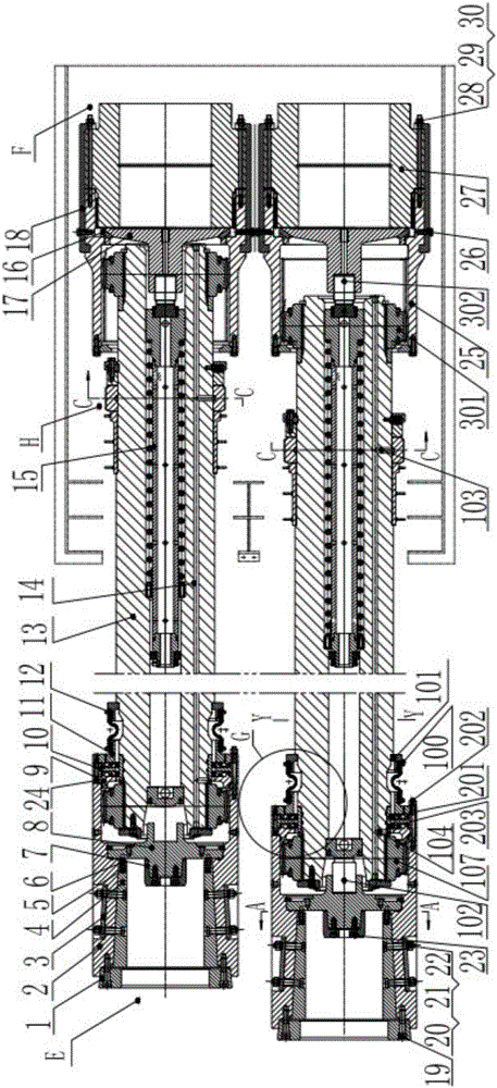
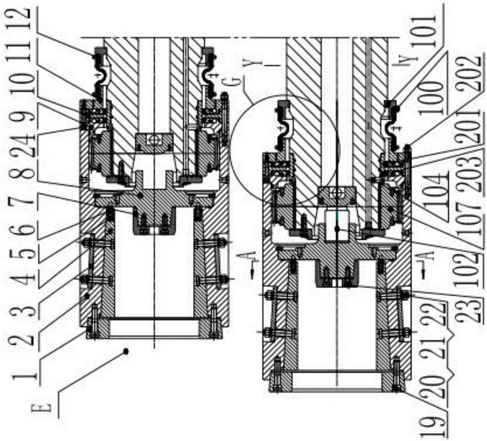
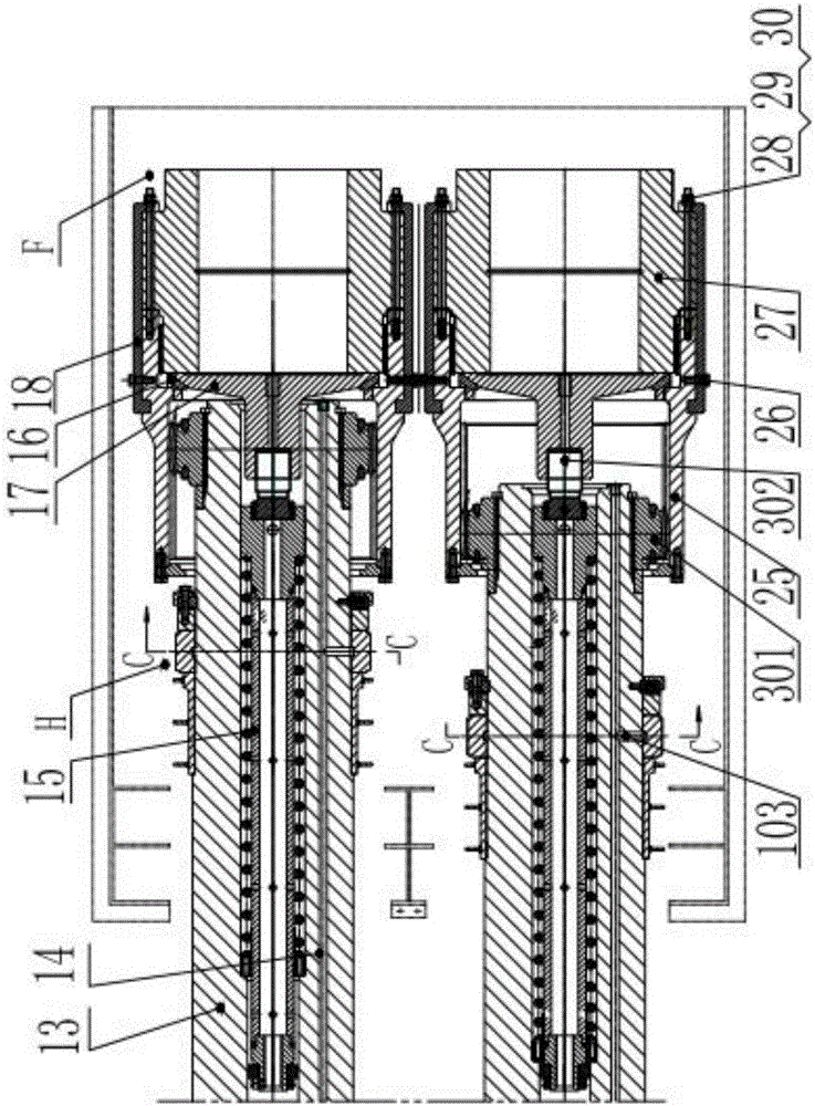
[0087] The present invention is an adjustable thin oil lubricated drum gear coupling, which includes a main shaft 13, a roller end assembly E, a gear end assembly F, an oil inlet ring assembly H, a spring assembly 15, and a roller end assembly E 1. The tooth end assembly F and the oil inlet ring assembly H are arranged on the main shaft 13, the spring assembly 15 is arranged in the main shaft 13, and the roller end assembly E is an adjustable roller end assembly, which includes a roller end bushing, a roller end connection plate 8, Outer centering 1, inner centering 7, roll end jacking block 102, roll end outer ring gear 107, roll end connecting disc 8 and outer centering 1 are all connected to the roll end bushing, inner centering 7 and roll end jacking block 102 are all Connected with the roller end connection plate 8, the roller end bushing meshes with the roller end outer ring gear 107 through internal teeth, and the roller end outer ring gear 107 cooperates with the main s...

Embodiment 2

[0089] The roller-end bushing is a split-type roller-end bushing, which includes a roller-end bushing body 2 and two lining plates 4, and the two lining plates 4 are symmetrically arranged in the flat groove of the inner hole of the roller-end bushing body 2 Inside, the two are bonded by an inclined surface; the lining plate 4 is fastened in the flat groove of the inner hole of the roller end sleeve body 2 through the pressure plate 3, the hinge bolt 20, the elastic washer 21 and the nut 22.

[0090] In this way, by loosening the fastener and the pressing plate, the lining plate moves along the inclined plane, and the size of the dimension B between the two lining plates can be changed, so that it is suitable for occasions where the connection size is restored after wear and the connection size is different.

Embodiment 3

[0092]The outer centering 1 described above is an expansion-contraction type external centering, and the outer circle of the expansion-contraction type outer centering 1 cooperates with the left notch of the roller end sleeve body 2 through a tapered surface, and is fastened on the Inside the left seam of the roller end bushing body 2.

[0093] In this way, the inner circle diameter φD of the outer centering 1 can be changed by moving the outer centering on the tapered surface and tightening (loosening) the screw 19, so that it is suitable for restoring the connection size and different connection sizes after wear.


PUM


Abstract

The invention discloses a thin oil lubrication drum-shaped tooth type coupling which comprises a spindle, a roller end assembly E, a tooth end assembly F, an oil inlet ring assembly H and a spring assembly. The roller end assembly E, the tooth end assembly F and the oil inlet ring assembly H are arranged on the spindle. The spring assembly is arranged in the spindle. The roller end assembly E is an adjustable roller end assembly and comprises a roller end shaft sleeve, a roller end connecting disc, an outer centering, an inner centering, a roller end top block and a roller end outer tooth ring. The roller end connecting disc and the outer centering are connected with the roller end shaft sleeve. The inner centering and the roller end top block are connected with the roller end connecting disc. The roller end shaft sleeve is engaged with the roller end outer tooth ring through inner teeth. The roller end outer tooth ring is matched with the spindle. By adoption of the thin oil lubrication drum-shaped tooth type coupling, the defects of existing thin oil lubrication drum-shaped tooth type couplings are overcome, the overall service life of the thin oil lubrication drum-shaped tooth type coupling is prolonged, and the requirements of continuous rolling mill characteristics are met; and meanwhile, the production cost of a hot continuous rolling factory is also lowered, and benefits are created.

Description

technical field [0001] The invention relates to a drum-shaped gear coupling, in particular to a drum-shaped gear coupling for a thin-plate strip steel hot-rolling continuous rolling finish rolling unit, a continuous casting and continuous rolling unit and a rough rolling main drive. Background technique [0002] The advanced technology of modern metallurgical production such as thin slab continuous casting and rolling (CSP) requires large-scale, efficient and high-precision rolling equipment, so it poses new challenges to the related spare parts industry. For thin plate and strip steel hot rolling and continuous rolling finishing mills and continuous casting and continuous rolling mills, since the main drive shaft is the key transmission component of the entire continuous rolling equipment, its performance and quality are directly related to the output and quality of strip products , its technical requirements are getting higher and higher. [0003] The structure of the exi...

Claims


Application Information

Patent Timeline
Patent Type & Authority Applications(China)
IPC IPC(8): B21B35/14F16N1/00
CPCB21B35/14B21B35/147
Inventor 张殿龙雷海涛
Owner TAIER HEAVY IND
Why Eureka
Try Eureka