Module for an automation device

a technology for automation devices and modules, applied in the direction of electrical apparatus construction details, furniture parts, semiconductor/solid-state device details, etc., can solve the problems of difficult work, problematic openings in the housing capsule below and above the components, etc., to facilitate the closure of the structural form, prevent thermal coupling of the modules, and dissipate heat

Active Publication Date: 2010-02-04
SIEMENS AG
View PDF31 Cites 2 Cited by
  • Summary
  • Abstract
  • Description
  • Claims
  • Application Information

AI Technical Summary

Benefits of technology

[0006]It is advantageous that the openings in the housing capsule below the electric and electronic components can be dispensed with and a closed structural form facilitated thereby. The side wall embodied as being thermally conductive is provided for dissipating heat from the module; the side wall embodied as being thermally insulated will prevent thermal coupling to an adjacent module of an assembled automation device. As thermal coupling of the modules is prevented, adjacent modules will not heat each other.
[0008]In a further embodiment of the invention it is provided for the electric components of the module, for example a printed circuit board fitted with electronic components, to be thermally coupled to the thermally conductive side wall. The removal of heat from the module will be further improved thereby.

Problems solved by technology

Said openings in the housing capsule below and above the components are problematic especially if the modules or automation device are / is employed in areas exposed to explosion hazards or in applications requiring a tight seal.
Moreover, adjacent modules in the automation device heat each other, a factor that has to be considered during project work on the automation device and which, owing to the modular automation device's wide-ranging combination potential, makes such work difficult.

Method used


Image

  • Module for an automation device
  • Module for an automation device
  • Module for an automation device

Examples


Embodiment Construction

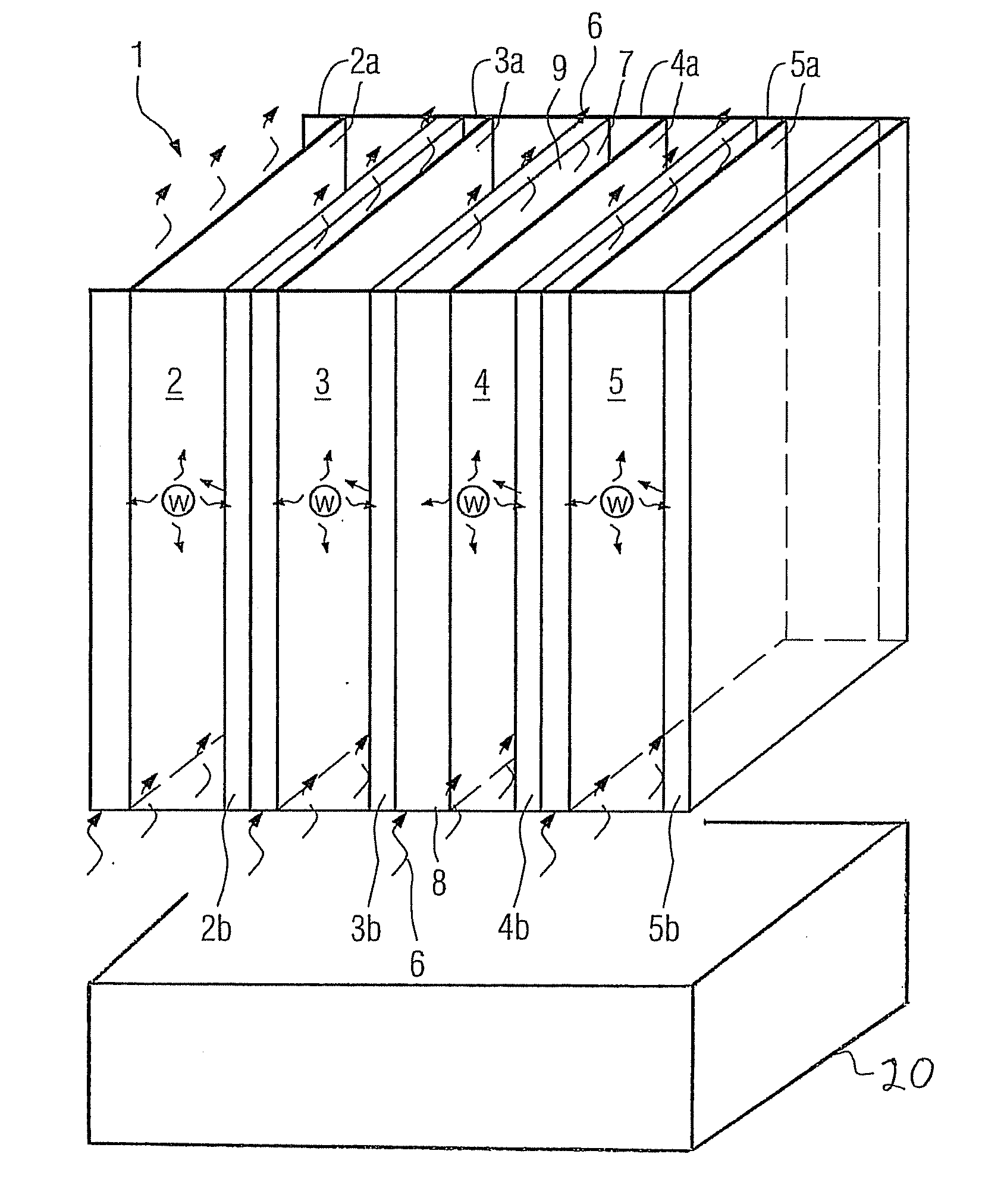
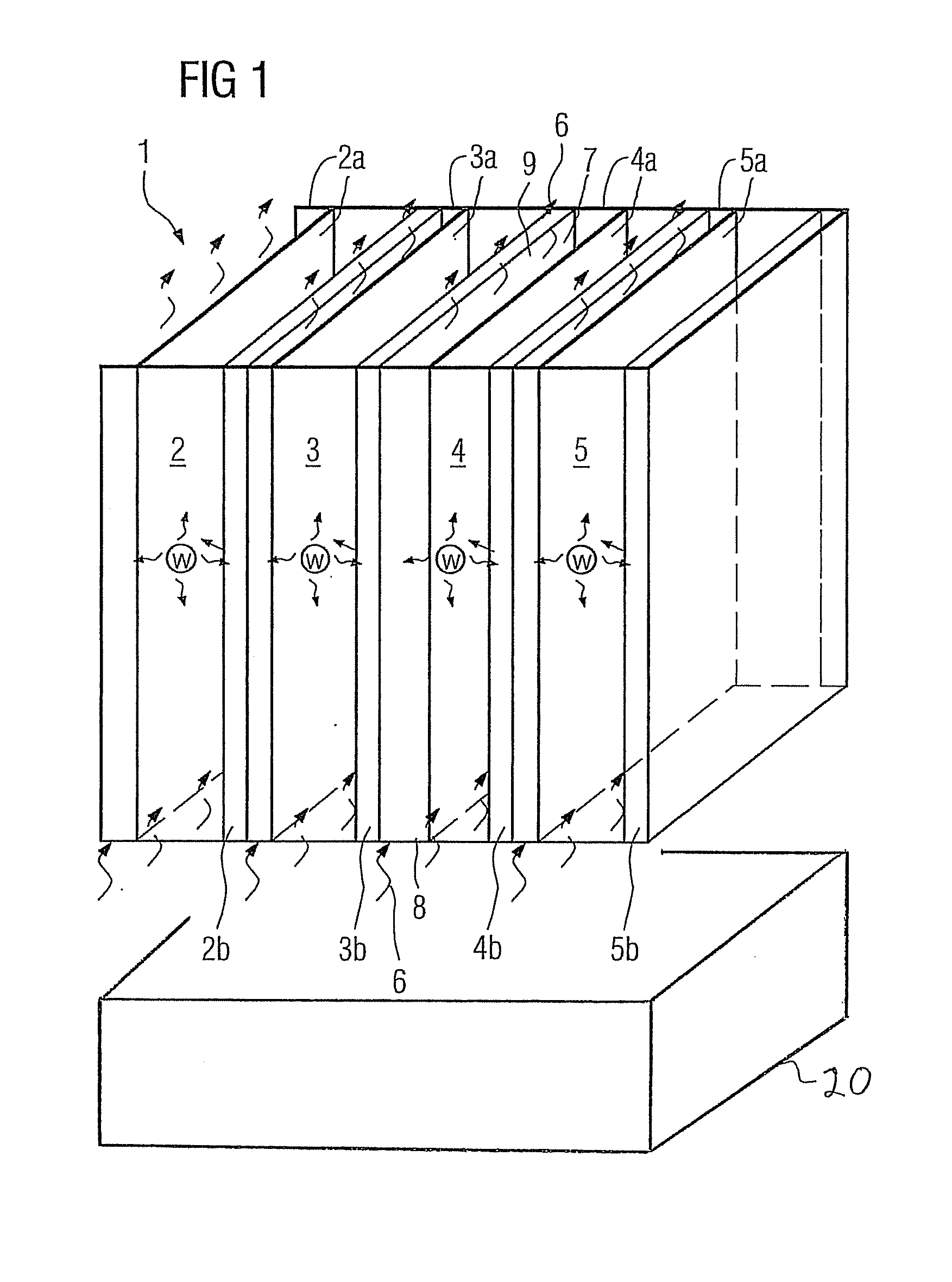
[0013]Identified by the numeral 1 in FIG. 1 is a modular automation device that includes four modules 2, 3, 4, 5 of equal width. Further constituents of the automation device 1, for example communication means via which the modules are interconnected or suitable hooking devices for attaching the modules to a support rail (not shown here), are of no significance to the invention and will not be elucidated in the following. The modules can of course be embodied as being of different width. It is, though, advantageous for visual or design reasons for the width of the modules to be made the same or having the same modularity (2×, 3× etc. width). The modules 2, 3, 4, 5 each have a thermally conductive u-shaped side wall 2a, 3a, 4a, 5a and each a thermally insulated side wall 2b, 3b, 4b, 5b, with in each case a thermally insulated side wall 2b, 3b, 4b, 5b of one module 2, 3, 4, 5 being adjacent to in each case a thermally conductive side wall 2a, 3a, 4a, 5a of a further module 2, 3, 4, 5....


PUM


Abstract

A module for an automation device with a plurality of adjacent modules is provided. The module includes a housing capsule that has at least one rear wall and two side walls and which is provided for housing electric components. Further, an automation device including the module is provided. One of the side walls of the modules is embodied as being thermally conductive and that the other side wall is embodied as being thermally insulated.

Description

CROSS REFERENCE TO RELATED APPLICATIONS[0001]This application is a continuing application of U.S. application Ser. No. 11 / 897,375 filed Aug. 30, 2007. This application claims priority of European Application No. 06018133.6 EP filed Aug. 30, 2006; both applications are incorporated by reference herein in their entirety.FIELD OF INVENTION[0002]The invention relates to a module for an automation device that consists of a plurality of adjacent modules, having a housing capsule that has at least one rear wall and two side walls and which is provided for housing electric components. The invention relates further to an automation device having modules of said type.BACKGROUND OF INVENTION[0003]An example of a module is known from Siemens' Catalog “ST 70 News 2006”, Section 3: “SIMATIC S7”. Located inside a housing capsule of the module is a printed circuit board fitted with electric and electronic components. Said components are cooled mainly through convection in a manner such that air flo...

Claims


Application Information

Patent Timeline
Patent Type & Authority Applications(United States)
IPC IPC(8): H05K7/20
CPCH05K7/20136H05K7/1468
Inventor ABERT, MICHAEL
Owner SIEMENS AG
Why Eureka
Try Eureka