Floor drain
A floor drain and floor drain cover technology, applied in the field of bathroom cleaning, can solve problems such as poor water flow, obstruction of drainage outlets, inconvenience, etc., and achieve the effect of good water sealing effect, smooth water flow, and prevention of blockage.
- Summary
- Abstract
- Description
- Claims
- Application Information
AI Technical Summary
Problems solved by technology
Method used
Image
Examples
Embodiment 1
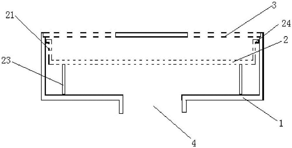
[0026] Refer to attached figure 1 As shown, the floor drain of the present invention includes a floor drain body 1 , a filter sieve tray 2 and a floor drain cover 3 .
[0027] The floor drain main body 1 includes a bottom and a side wall connected to the periphery of the bottom. The bottom of the floor drain main body 1 includes a central drain 4 and an annular platform arranged around the drain 4, preferably an annular platform. The drain port 4 is connected with the water inlet of the sewer pipe.
[0028] The filter sieve tray 2 is arranged inside the main body of the floor drain 1, which is a filter tray structure with side edges 21 around and sieve holes at the bottom, and a gap is provided between the lower surface of the filter sieve tray 2 and the upper surface of the above-mentioned annular platform . The gap can be formed by a plurality of support columns 23 fixedly arranged on the lower surface of the filter sieve tray 2 . This structure allows the sewage to flow ...
Embodiment 2
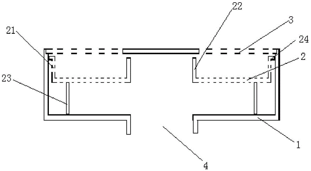
[0031] Refer to attached figure 2 As shown, this embodiment is improved on the basis of Embodiment 1. The improvement is that an opening is provided at the center of the filter sieve tray 2, and an annular enclosure 22 is provided at the opening. The annular enclosure The area 22 corresponds to the above-mentioned area of the floor drain outlet 4 and has the same size. The bottom of the filter disc outside the annular enclosure 22 is provided with a screen hole, and the annular enclosure 22 is not provided with a screen hole, which can play a role in dispersing and buffering the water flow. role.
[0032] The floor drain cover 3 is arranged on the upper port of the side wall of the above-mentioned floor drain main body 1, and it is a grid-shaped cover plate with a closed area in the center. The closed area corresponds to the area of the above-mentioned annular enclosure 22 and is slightly larger than the area of the annular enclosure. That is, the closed area can cover...
Embodiment 3
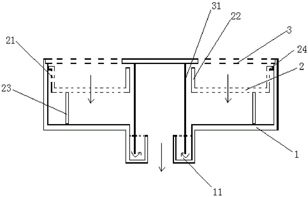
[0036] Refer to attached image 3 As shown, this embodiment is further improved on the basis of the second embodiment, and the improvement is that the floor drain of this embodiment can also have an anti-odor mechanism. The anti-odor mechanism includes an annular groove 11 arranged at the drain outlet 4 of the main body of the floor drain and an anti-odour ring 31 arranged at the bottom of the floor drain cover 3. The height of the inner annular side wall of the annular groove 11 is lower than that of the outer annular side of the annular groove 11. The height of the wall, ie below the upper surface of the annular platform. A preferred embodiment is that the height of the inner annular sidewall of the annular groove 11 is 20mm-30mm. The opening surrounded by the inner annular side wall of the annular groove 11 communicates with the water inlet of the sewer pipe.
[0037] The anti-smell ring 31 is arranged below the closed area of the floor drain cover body 3, and the outer...
PUM
 Abstract
Description
Claims
Application Information
 - R&D
- Intellectual Property
- Life Sciences
- Materials
- Tech Scout
- Unparalleled Data Quality
- Higher Quality Content
- 60% Fewer Hallucinations
Browse by: Latest US Patents, China's latest patents, Technical Efficacy Thesaurus, Application Domain, Technology Topic, Popular Technical Reports.
© 2025 PatSnap. All rights reserved.Legal|Privacy policy|Modern Slavery Act Transparency Statement|Sitemap|About US| Contact US: help@patsnap.com


