
Combined chain wheel

A technology of sprockets and runners, applied in the direction of belts/chains/gears, lubricating parts, lubricating oil control valves, etc., can solve problems such as difficult cleaning, affecting environmental sanitation, and wasting lubricating oil, and achieve the effect of even oiling

Active Publication Date: 2021-04-02
常州盛天传动科技有限公司
View PDF4 Cites 0 Cited by
  • Summary
  • Abstract
  • Description
  • Claims
  • Application Information

AI Technical Summary

Problems solved by technology

[0003] In the prior art, due to the large friction between the chain and the sprocket, in order to ensure the linkage of the transmission process and the slippage of the work efficiency, it is generally necessary to brush the chain with oil, thereby reducing the friction between the sprocket and the chain. friction, the existing oil brushing method achieves the purpose of oiling by pouring oil on the chain, and then adjusting the rotation of the whole chain, but this oiling method is easy to cause oil to drip from the chain, which not only affects environmental sanitation, but also wastes Most of the lubricating oil, and it makes the oiling of the chain uneven. At the same time, if it is directly applied manually, it will bring more trouble to the user. At this time, it is easy to stick the lubricating oil to the clothing and it is difficult to clean. In particular, When spraying lubricating oil, a large amount of lubricating oil will fall due to gravity. If it falls directly on the ground, it will not only easily cause environmental pollution, but also cause a large amount of lubricating oil to be wasted, causing a lot of economic burden to the manufacturer

Method used


Image

  • Combined chain wheel
  • Combined chain wheel
  • Combined chain wheel

Examples


Embodiment approach

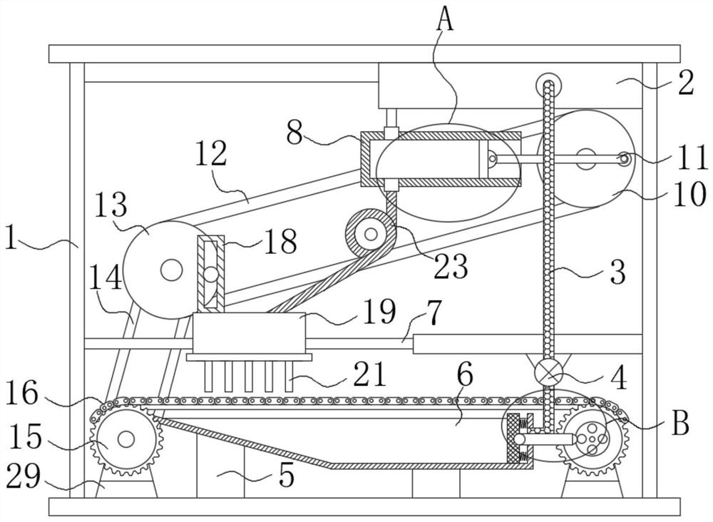
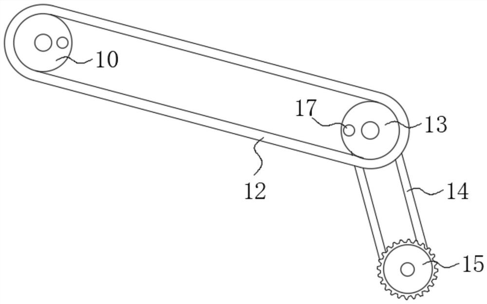
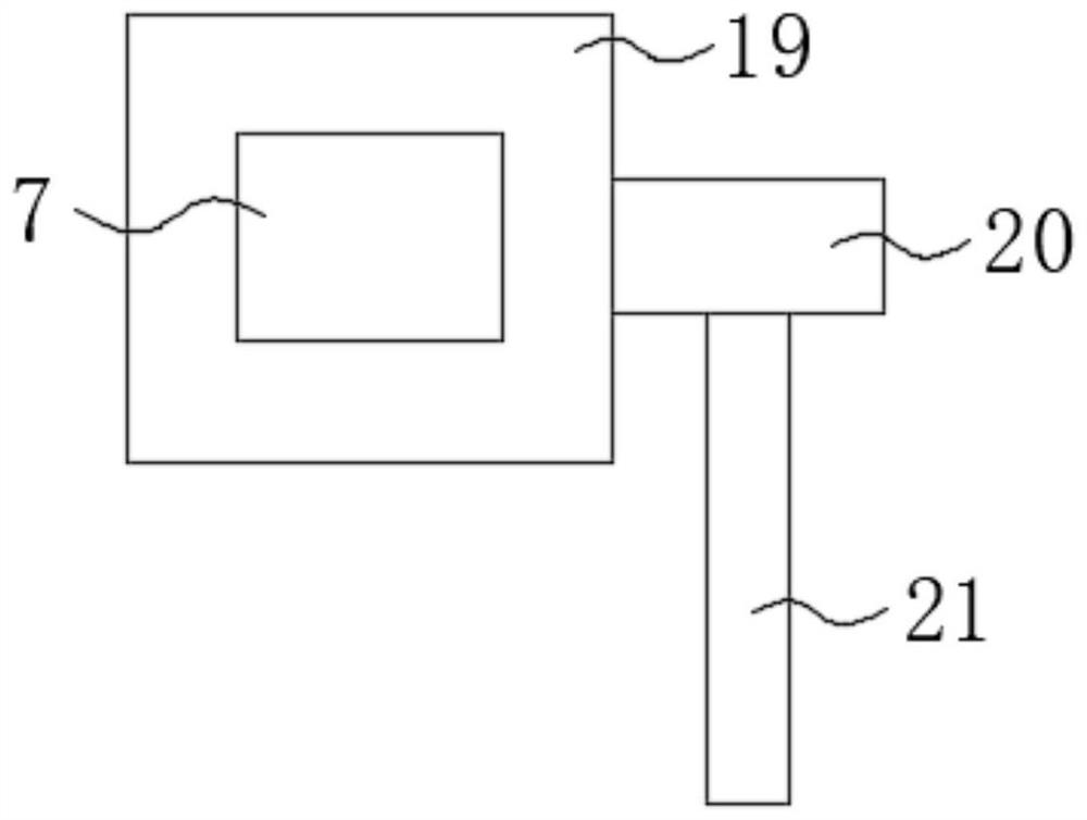
[0036] As an embodiment of the present invention, the oiling mechanism is composed of an installation frame 18, a movable block 19, a collection box 20, an oil injection nozzle 21 and a material guide hose 23, and the movable block 19 is slidably connected to the outer surface of the installation frame 18, The mounting frame 18 is fixedly connected to the upper end of the movable block 19, the outer wall of the round block 17 is slidably connected to the inner wall of the mounting frame 18, and the width of the round block 17 is equal to the width of the inner wall of the mounting frame 18, and the collecting box 20 is fixedly connected to the movable block. 19, the oil injection nozzle 21 is fixedly connected to the lower end of the collection box 20, and one end of the material guide hose 23 is fixedly connected to the upper end of the collection box 20, and the check valve body 22 is provided with two pieces, two check valves The bodies 22 are fixedly connected to the upper ...


PUM


Abstract

The invention discloses a combined chain wheel. The combined chain wheel comprises a frame body, a material storage box, a feeding pipe, a liquid conveying pump and supporting legs, wherein the material storage box is fixedly connected to the inner wall of the upper side of the frame body, the feeding pipe is fixedly connected to the front side of the material storage box, the liquid conveying pump is installed in the middle of the feeding pipe, the supporting legs are fixedly connected to the inner wall of the lower side of the frame body, a collecting tank is fixedly connected to the upper ends of the supporting legs, a liquid filtering mechanism is installed on the inner wall of the collecting tank, and a limiting rod is fixedly connected to the inner wall of the frame body. When the combined chain wheel is in use, because structures such as a sleeve and a piston are used in cooperation, the effect of convenient oil discharging is achieved; because a round block, a mounting frame and the like are used in cooperation, the effect of uniform oiling is achieved; because the collecting tank, a chain body and the like are used in cooperation, the chain body and the like, the effect ofautomatically collecting dripped lubricating oil is achieved; and because an inserting rod, a filter screen and the like are used in cooperation, the pre-filtering effect is achieved.

Description

technical field [0001] The invention belongs to the technical field of combined sprockets, in particular to a combined sprocket. Background technique [0002] The sprocket is a wheel with cog-type buckle teeth, which is used to mesh with the accurate pitch blocks on the chain link or cable. The sprocket is widely used in chemical industry, textile machinery, food processing and instrumentation, etc. In the mechanical transmission industry, etc., the sprocket is usually used in conjunction with the chain, which can transmit motion and power when the center distance between the two axes is far away, and can work under low speed, heavy load, high temperature and dusty conditions, and can ensure Accurate transmission ratio, larger transmission power, less force acting on the shaft, high transmission efficiency. [0003] In the prior art, due to the large friction between the chain and the sprocket, in order to ensure the linkage of the transmission process and the slippage of t...

Claims


Application Information

Patent Timeline
Patent Type & Authority Applications(China)
IPC IPC(8): F16H57/05F16N7/34F16N7/38F16N23/00F16N31/02F16N39/06
CPCF16H57/05F16H57/0458F16H57/0434F16H57/0421F16H57/0435F16H57/0404Y02P70/10
Inventor 汪忠诚王晓丽
Owner 常州盛天传动科技有限公司
Learn More