A sealed connection structure and a connector using the sealed connection structure

A technology of connection structure and connection surface, applied in the direction of base/shell, etc., can solve the problems of connection failure and inability to seal well, and achieve the effect of high connection strength

Active Publication Date: 2018-01-16
CHINA AVIATION OPTICAL-ELECTRICAL TECH CO LTD
View PDF6 Cites 1 Cited by
  • Summary
  • Abstract
  • Description
  • Claims
  • Application Information

AI Technical Summary

Problems solved by technology

[0004] The purpose of the present invention is to provide a sealing connection structure with a reliable seal between the sealing rubber pad and the mounting plate, which is used to solve the problem that the sealing rubber pad used in the prior art can not be sealed well due to connection failure or wear. problem; at the same time, the present invention also provides a connector using the sealed connection structure

Method used


Image

  • A sealed connection structure and a connector using the sealed connection structure

Examples


Embodiment 1

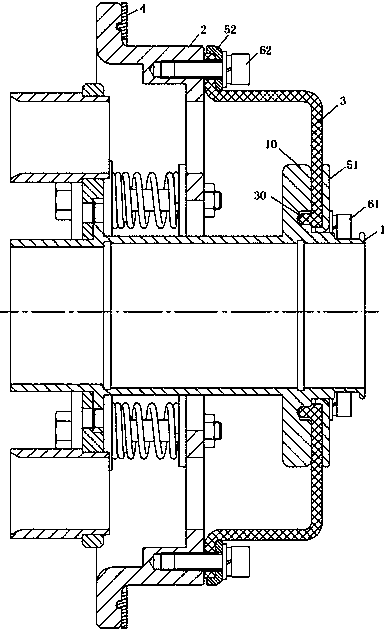
[0014] Embodiment 1 of the connector of the present invention: as figure 1 As shown, it includes an inner shell 1 and an outer shell 2 whose axis extends left and right. The left end of the outer shell is provided with an outer flange for fixed connection with the fixed plate, and a gasket 4 is provided between the outer flange and the fixed plate. The inner shell 1. The floating connection is inside the outer shell 2. There is a floating gap between the inner shell 1 and the outer shell 2 for the inner shell to float radially. The connector also includes a seal for sealing the floating gap between the inner shell and the outer shell. The connection structure, the sealing connection structure includes a fixed base and a flexible sealing sleeve 3, the fixed base is provided with a sealing connection surface for connecting the flexible sealing sleeve, the flexible sealing sleeve is connected to the sealing connection surface through a connecting piece and an annular pressure plat...

Embodiment 2

[0021] Embodiment 2 of the connector of the present invention: the difference from Embodiment 1 is that the connector only includes an outer sealing connection structure, and the inner edge of the flexible sealing sleeve is directly bonded to the inner housing.

Embodiment 3

[0022] Embodiment 3 of the connector of the present invention: the difference from Embodiment 1 is that the connector only includes an inner sealing connection structure, and the outer edge of the flexible sealing sleeve is directly bonded to the outer shell.

[0023]Embodiment 4 of the connector of the present invention: the difference from Embodiment 1 is that the connector only includes an outer sealing connection structure, and the inner edge of the flexible sealing sleeve is crimped to the inner housing through the flange provided on the inner housing superior.

[0024] Embodiment 5 of the connector of the present invention: the difference from Embodiment 1 is that the inner and outer concave-convex structures are mutually matched convex and concave structures that are evenly distributed in the circumferential direction, and the sealing connection surface of the outer shell and the flexible sealing sleeve. rise and groove.

[0025] Embodiment 6 of the connector of the pr...


PUM


Abstract

The invention provides a sealed connection structure and a connector using the sealed connection structure, wherein the sealed connection structure includes a fixed base and a flexible sealing sleeve, the fixed base is provided with a sealing connection surface for connecting the flexible sealing sleeve, and the flexible sealing sleeve passes through The connecting piece and the annular pressure plate are connected on the sealing connection surface, and the outer edge and / or inner edge of the annular pressure plate are provided with a limiting structure extending toward the sealing connection surface for limiting the amount of compression deformation of the flexible sealing sleeve. The sealing connection structure of the present invention connects the flexible sealing sleeve to the sealing connection surface of the fixed base through the connecting piece and the annular pressure plate. Compared with the connection with the mounting plate through the self-deformation of the sealing rubber sleeve, the connection strength is high, and the connection will not cause failure. At the same time, the limit structure can limit the amount of compression deformation of the flexible sealing sleeve, preventing the sealing rubber sleeve from being over-compressed beyond the deformation limit and losing its elasticity, which cannot achieve a sealing effect.

Description

technical field [0001] The invention relates to a sealing connection structure suitable for an electric connector and a connector using the sealing connection structure. Background technique [0002] Electrical connectors play a very important role in electrical equipment, and with the expansion of the application field of electrical equipment, the application environment of electrical connectors also expands. For example, the Chinese utility model patent whose authorized announcement number is CN201508953U and whose authorized announcement date is 2010.06.16 discloses a floating sealing rubber pad and a connector equipped with a good sealing rubber pad. There is a floating gap between the mounting holes of the board and can float radially in the mounting hole relative to the mounting board. In order to prevent water leakage between the connector and the mounting board, the connector housing is also provided with a sealed connection structure, that is, a floating sealing rub...

Claims


Application Information

Patent Timeline
Patent Type & Authority Patents(China)
IPC IPC(8): H01R13/52
Inventor 郭辉李彩涛李永棒
Owner CHINA AVIATION OPTICAL-ELECTRICAL TECH CO LTD
Why Eureka
Try Eureka