
A kind of anti-loosening socket

A socket and anti-loose technology, applied in the direction of the base/shell, coupling device, magnetic object, etc., can solve the problem of poor contact between the reed and the plug, and achieve the effect of preventing poor contact and prolonging the service life.

Active Publication Date: 2020-10-09
南通鑫生派智能科技有限公司
View PDF12 Cites 0 Cited by
  • Summary
  • Abstract
  • Description
  • Claims
  • Application Information

AI Technical Summary

Problems solved by technology

[0005] The invention provides an anti-loosening socket, aiming to solve the problem of poor contact between the reed and the insertion piece in the prior art

Method used


Image

  • A kind of anti-loosening socket
  • A kind of anti-loosening socket
  • A kind of anti-loosening socket

Examples


Embodiment

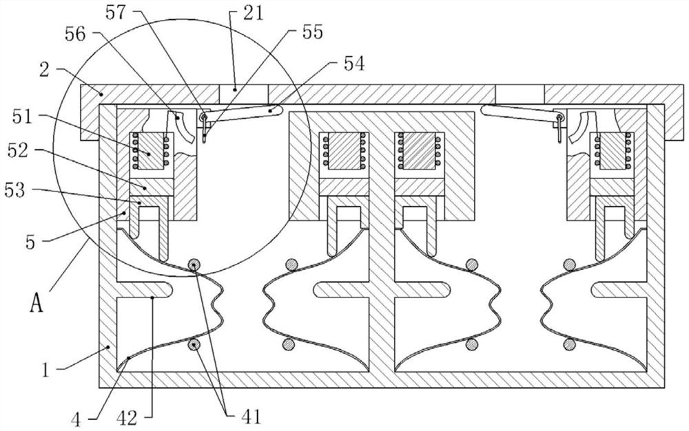
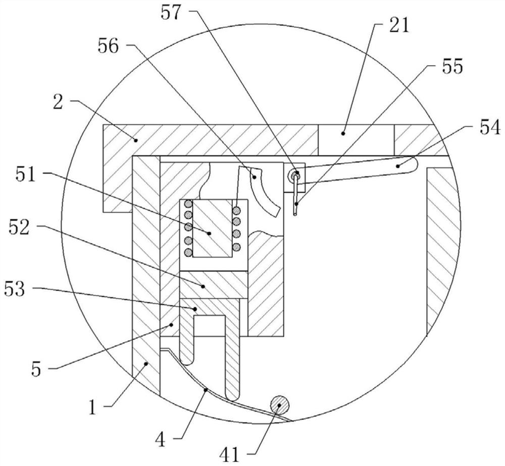
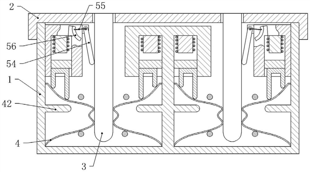
[0026] Embodiment 1, a kind of anti-loosening socket, such as figure 1 As shown, it includes a socket body 1, an upper cover 2 and a reed 4. The upper cover 2 is provided with a jack, and the reed 4 is provided with an arc-shaped raised portion that contacts the insertion piece 3. The raised portion is provided with two Two arc-shaped protrusions, when the insert 3 is inserted into the socket and contacts the reed 4, the two arc-shaped protrusions make the reed 4 and the insert 3 form a multi-point contact, which is beneficial to reduce the contact between the reed 4 and the insert. 3 friction and increased conductivity, a rectifier is provided in the socket body, and the rectifier is electrically connected to the socket power supply, and a fixing rod 41 is set on the upper and lower sides of the outer side of the arc-shaped protrusion of the reed 4, and the fixing rod 41 is connected to the socket body 1 Fixedly connected, the fixed rod 41 is contacted and connected with the ...

Embodiment 2

[0030] Embodiment 2: The difference from Embodiment 1 is that: the resistance plate 56 and the metal slide bar 55 are canceled, and a push switch 31 is provided on the bottom plate of the socket body corresponding to the jack 21, and the push switch 31 is connected in series to one of the rectifiers. between one output power line and one end of the electromagnet coil, and the other end of the electromagnet coil is electrically connected to another output power line of the rectifier.

[0031] The working process of the second embodiment is: when the insertion piece 3 is not inserted into the socket, the rotating plate 54 blocks the jack 21 under the elastic force of the torsion spring, and when the insertion piece 3 is inserted through the jack 21, the insertion piece 3 pushes the rotating plate 54 Rotating around the rotating shaft 57, when the insert piece 3 is inserted into the socket body and presses the push switch 31 on the bottom plate, the coil of the electromagnet 51 is...


PUM


Abstract

The invention relates to the field of the power supply distribution, and specifically relates to an anti-loose socket. The socket comprises a socket body, an upper cover and a reed; an arc boss contacting with an inserted slice is arranged on the reed, and an extrusion device fixedly connected with a socket body is further arranged in the socket body; the extrusion device is arranged at an upper space of the reed, and comprises an electromagnet and a magnet block; a push plate is arranged the bottom of the magnet block; one end of a coil of the electromagnet is electrically connected with oneof power lines, and the other end is electrically connected with a resistor arranged on an outer wall of the extrusion device; the sidewall of one side, close to the jack, of the extrusion device is rotatably connected with a rotating plate through a rotating shaft, and a metal sliding rod is arranged on the rotating plate; when the rotating plate downwards rotates, a free end of the metal slidingrod is in sliding connection with the resistor, one end, fixedly connected with the rotating plate, of the metal sliding rod is electrically connected with the other end of the power line. Through the anti-loose socket disclosed by the invention, the reed of the socket presses the inserted slice to prevent the bad contact of the inserted slice and the reed.

Description

technical field [0001] The invention relates to the field of power distribution, in particular to an anti-loosening socket. Background technique [0002] Common household sockets and plugs fit together. When the plug of the plug is inserted into the socket and contacts the reed to conduct electricity, the reed is squeezed by the plug to cause the deformation of the reed to produce elastic force. The elasticity of the reed is used to maintain the contact between the reed and the plug. Clamping force, with the prolongation of the use of the socket, the spring force of the reed will decrease, and the pressure on the insert will become smaller, and the clamping force will become smaller, causing the plug to loosen. It is easy to cause a bad contact of the plug or a disconnection from the socket to cause a power outage. This sudden power failure will cause damage to electrical appliances. [0003] Most of the existing anti-loosening sockets adopt a closed structure to prevent th...

Claims


Application Information

Patent Timeline
Patent Type & Authority Patents(China)
IPC IPC(8): H01R13/62H01R13/639H01R13/66H01R13/703H01R13/05H01R13/453H01R13/502H01R13/52H01F7/08H01F7/16
CPCH01F7/081H01F7/1638H01R13/055H01R13/4536H01R13/502H01R13/5213H01R13/62H01R13/639H01R13/6616H01R13/6633H01R13/7035
Inventor 彭娇娇李曙东
Owner 南通鑫生派智能科技有限公司
Learn More