Limiting structure of detachable lifting boiler

A technology of limit structure and clamping structure, which is applied in the field of limit pieces and limit structures of detachable lift boilers, can solve the problem of inability to fix the height of the screw

Pending Publication Date: 2018-05-15
范启鑫
View PDF0 Cites 0 Cited by
  • Summary
  • Abstract
  • Description
  • Claims
  • Application Information

AI Technical Summary

Problems solved by technology

[0004] The purpose of the present invention is to solve the problem that the height of the screw cannot be fixed when the lifting boiler in the prior art is manufactured as a detachable type, and to provide a limit structure for a detachable lifting boiler, which has a pot body and a base that can be separated while fixing the screw , making it non-rotating and non-falling

Method used


Image

  • Limiting structure of detachable lifting boiler
  • Limiting structure of detachable lifting boiler
  • Limiting structure of detachable lifting boiler

Examples


specific Embodiment 1

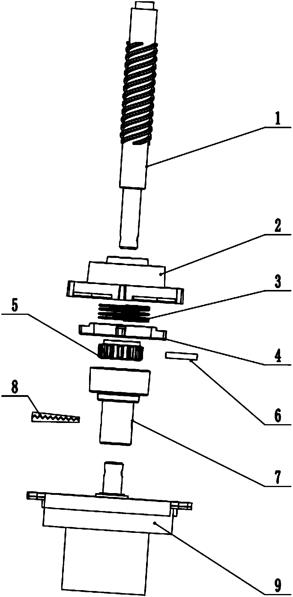
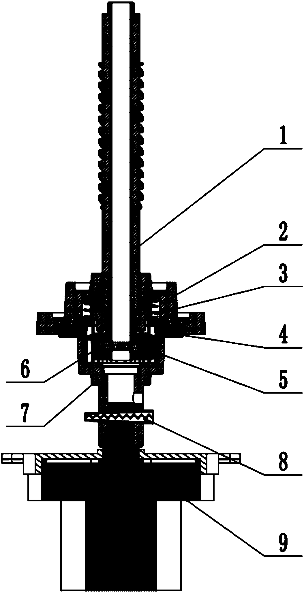
[0024] refer to figure 1 , 2 , 5 In this embodiment, it includes a lock nut 2, an elastic member 3, a rotation stop member 4, a rotating gear 5, a motor connector 7, and a motor 9, and its structural characteristics are: the motor connector 7 has a The connecting part of the connecting part and the interlocking part with the rotating gear 5 are mutually nested. The motor extends upwards from the motor shaft, and the motor shaft is connected to the motor connecting part 7 through the bolt 8. The middle part of the lock nut 2 is provided with a basic accommodation elastic part 3 and a stopper. In the section of the rotating part 4, the elastic part 3 supports the anti-rotating part 4, when the elastic part 3 or the magnetic part 10 is compressed, the anti-rotating part 4 is embedded in the lock nut 2, and when the elastic part 3 is in a normal state, the anti-rotating part 4 is higher than the locking nut 2 And mesh with the rotating gear 5; one end of the screw 1 passes throug...

specific Embodiment 2

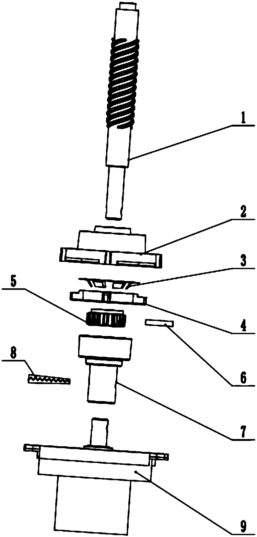
[0027] refer to image 3 In this embodiment, the elastic member 3 is an elastic plastic ring; other parts are consistent with the specific embodiment 1.

specific Embodiment 3

[0028] refer to Figure 4 Compared with the specific embodiment 1, in this embodiment, the elastic part 3 is replaced by a magnetic part 10, and the magnetic part 10 is respectively arranged in the lock nut 2 and on the anti-rotation part 4, and inside the lock nut 2 and on the anti-rotation part 4 The magnetic parts 10 on the top are oppositely arranged for the magnetic poles of the same name.

[0029] refer to Figures 1 to 4 In the above three specific embodiments, the motor connector 7 has a connecting portion for plug connection and a linkage portion that is nested with the rotating gear. The motor 9 protrudes upwards from the motor shaft, and the motor shaft is connected with the motor 9 connector through a bolt. The motor connector 7 and the rotating gear are cooperatingly socketed to realize the indirect connection between the motor 9 and the screw rod 1, and realize the detachability between the lifting hot pot motor 9 and the lifting assembly.

[0030] The two end...


PUM


Abstract

The invention relates to a limiting member, in particular to a limiting structure of a detachable lifting boiler, and belongs to the technical field of limiting components. The limiting structure comprises a locking nut, an elastic piece or magnetic piece, a rotation stop piece, a rotary gear, a motor connection piece and a motor. The limiting structure is structurally characterized in that the motor connection piece comprises a connection portion and a linkage portion, the connection portion is connected with a latch, and the linkage portion and the rotary gear are sleeved; a motor shaft is extended from the motor upwardly, and is connected with the motor connection piece through the latch; a section for basically accommodating the elastic piece or the magnetic piece and the rotation stoppiece is formed in the middle of the locking nut; the rotation stop piece is supported by the elastic piece or the magnetic piece. The limiting structure has the advantages that a boiler body and a base are detachable, a screw rod is protected from rotational descending due to gravity, the design is humanized, and safety and reliability are realized.

Description

technical field [0001] The invention relates to a limiting member, in particular to a limiting structure for a detachable lifting boiler. It belongs to the technical field of limit components. Background technique [0002] In the prior art, there is a lifting boiler ZL2016212602872. If it needs to be cleaned, the cooking stainless steel pot body and its lower base cannot be separated, so it needs to be cleaned as a whole. If it is not operated properly, it will easily cause the circuit to get wet and cause safety hazards. This kind of lifting hot pot is driven by a motor. The motor realizes the forward and reverse rotation of the screw through the cooperation of the bolt and the screw. If the screw rod breaks away from the latch, the screw rod will easily slip off without the support of other workpieces. For example, when the lifting boiler ZL2016212602872 is designed so that the base and the pot body can be separated, if the whole lifting boiler needs to be cleaned or the...

Claims


Application Information

Patent Timeline
IPC IPC(8): A47J36/00A47J36/34
CPCA47J36/00A47J36/34
Inventor 范启鑫
Owner 范启鑫
Why Eureka
Try Eureka