Sliding door-and-window edge fixing structure

A technology for sliding doors and windows and sliding fans, which is applied in the directions of windows/doors, building components, window/door frames, etc., can solve the problems of no protection measures against falling of the fan frame, inability to open the opening, and being located on the outside of the outer track, etc. Rainwater pouring and splashing, convenient and quick disassembly and assembly, and the effect of avoiding high-altitude falling

Inactive Publication Date: 2019-11-29
安徽永盛精工科技有限公司
View PDF0 Cites 0 Cited by
  • Summary
  • Abstract
  • Description
  • Claims
  • Application Information

AI Technical Summary

Problems solved by technology

Most of the traditional sliding doors and windows have a structure with more than two tracks. When there is a need for fixed fans, it is difficult to connect the fan frame and the outer frame firmly due to track problems.
The sliding doors and windows of the prior art have edge-fixed structures, but most of them have the fixed leaf on the inner side and the opening leaf on the outer track. For the opening leaf with a handle, since the handle in the open state is in a horizontal state, the handle will interfere with the fixed leaf , resulting in the opening of the hole cannot achieve the maximum opening amount; and the opening fan is located outside the outer track, there is no protection for the fan frame from falling; some sliding doors and windows with side-fixed structures, the glass pressure line of the fixed part faces the outside, which is very important for the installation and disassembly of the glass in the future It needs to be disassembled outdoors, which is difficult and unsafe

Method used


Image

  • Sliding door-and-window edge fixing structure
  • Sliding door-and-window edge fixing structure
  • Sliding door-and-window edge fixing structure

Examples


Embodiment Construction

[0025] The embodiments of the present invention are described in detail below. This embodiment is implemented on the premise of the technical solution of the present invention, and detailed implementation methods and specific operating procedures are provided, but the protection scope of the present invention is not limited to the following implementation example.

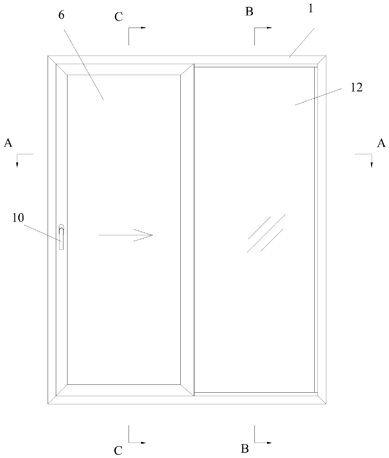
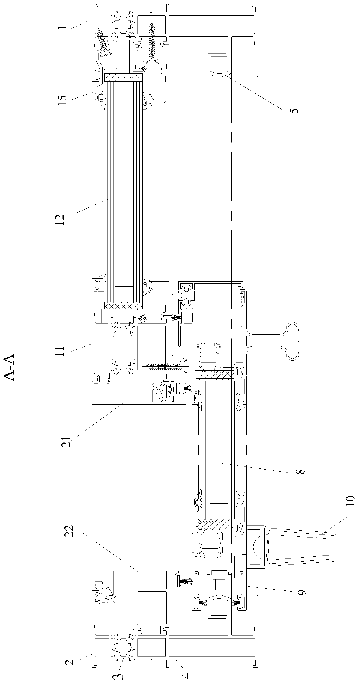
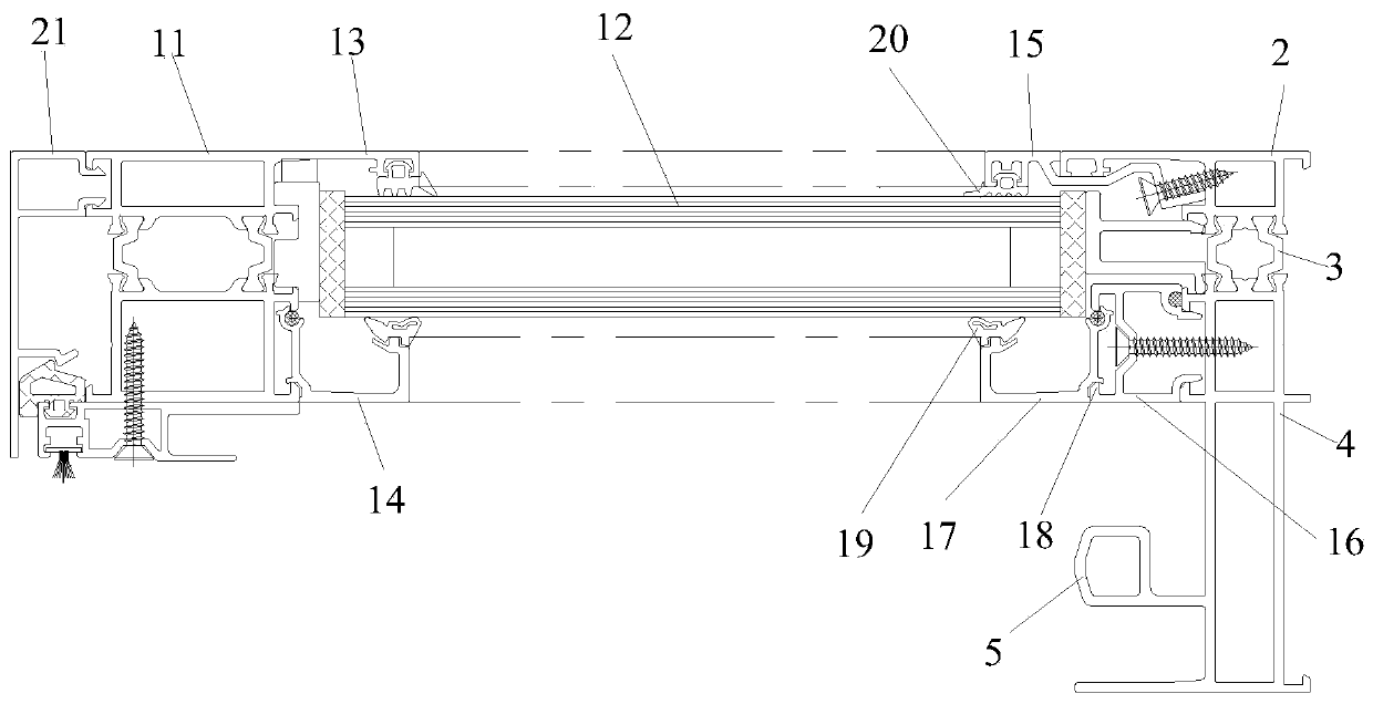
[0026] see Figure 1 to Figure 6 , this embodiment discloses a side-fixing structure for sliding doors and windows, including an outer frame 1, the outer frame 1 is surrounded by upper, lower, left and right sides, and the outer frame 1 includes outer frame outer profiles 2, The outer frame heat-insulating strip 3, the outer frame inner profile 4, the outer frame outer profile 2 and the outer frame inner profile 4 are connected together through the outer frame heat-insulating strip 3.

[0027] A track 5 is provided at the inner profile of the profile 4 inside the outer frame, and a push-pull fan 6 is slidably arra...


PUM


Abstract

The invention discloses a sliding door-and-window edge fixing structure. The sliding door and window edge fixing structure comprises an outer frame, the outer frame includes an outer frame outer sideprofile, an outer frame heat insulation penetrating strip and an outer frame inner side profile, the inner portion of the outer frame inner profile is provided with a track, and a sliding sash is arranged on the track; the middle part of an opening of the outer frame is provided with a vertical column located at the outer side of the sliding sash, the vertical column divides the opening of the outer frame into two areas, fixed glass is fixedly arranged in one area, the side, close to the vertical column, of the fixed glass is embedded in the vertical column, the other three sides of the fixedglass are correspondingly connected with the outer frame through connecting parts, the connecting parts include auxiliary adding single arms, supporting profiles and supporting pressing lines, the supporting pressing lines and the auxiliary adding single arms are respectively located on the inner side and the outer side of the fixed glass, so as to limit the inner and outer sides of the fixed glass. Compared with the prior art, the sliding door-and-window edge fixing structure has the advantages that convenient and safe disassemble and assembly of sliding doors and windows are achieved, and atthe same time, the large opening amount can be guaranteed.

Description

technical field [0001] The invention relates to the technical field of door and window installation structures, in particular to a side fixing structure for sliding doors and windows. Background technique [0002] In modern buildings, sliding doors and windows are often used for ventilation, beauty and convenience. Most of the traditional sliding doors and windows have a structure with more than two tracks. When there is a need for fixed leaves, it is difficult to connect the fan frame and the outer frame firmly due to track problems. The sliding doors and windows of the prior art have edge-fixed structures, but most of them have the fixed leaf on the inner side and the opening leaf on the outer track. For the opening leaf with a handle, since the handle in the open state is in a horizontal state, the handle will interfere with the fixed leaf , resulting in the opening of the hole cannot achieve the maximum opening amount; and the opening fan is located outside the outer tr...

Claims


Application Information

Patent Timeline
Patent Type & Authority Applications(China)
IPC IPC(8): E06B3/46E06B3/58E06B1/36E06B7/26
CPCE06B1/36E06B1/366E06B3/4618E06B3/5807E06B7/26
Inventor 陈长江朱成榕程鹏王金萍
Owner 安徽永盛精工科技有限公司
Why Eureka
Try Eureka