Manually controlled or electrically controlled door locking device

A door lock and electric control technology, applied in the field of locks, can solve the problems of poor telescopic response, complex internal structure, poor effect, etc., and achieve the effect of installing the lock body in different directions on the left and right, reasonable structural design, and better anti-theft function

Active Publication Date: 2016-04-13
佛山市思歌锁业科技有限公司
View PDF8 Cites 7 Cited by
  • Summary
  • Abstract
  • Description
  • Claims
  • Application Information

AI Technical Summary

Problems solved by technology

[0004] Although the anti-theft performance of this type of electronically controlled lock is good, it will have the following disadvantages: first, this type of electronically controlled lock can only be unilaterally driven by the motor. , the lock cannot be unlocked manually or by other means, and the door can only be opened after the lock body is disassembled for maintenance, or even the deadbolt is destroyed.
Second, the driving structure of this type of electronically controlled lock generally includes a clutch. After long-term use, the elastic expansion pin of the clutch is also prone to poor expansion and contraction response, or the clutch block is worn, resulting in failure of the clutch drive and affecting the service life.
Third, the transmission structure of this type of electronically controlled lock often includes several transmission gears, transmission dials, return springs and other components. The structure is complex, and the production and maintenance costs are high.
[0005] It can be seen that the electric control locks currently on the market have many defects due to their complex internal structure and unreasonable design, short service life and poor effect.

Method used


Image

  • Manually controlled or electrically controlled door locking device
  • Manually controlled or electrically controlled door locking device
  • Manually controlled or electrically controlled door locking device

Examples


Embodiment Construction

[0035] Below in conjunction with accompanying drawing, door lock device of the present invention is further elaborated in detail:

[0036] It should be noted that, for the convenience of disassembly and maintenance, the panel in the embodiment includes an outer panel and an inner panel, and the inner panel is detachably arranged on the inner side of the outer panel and used for installing other components. During maintenance, it is only necessary to disassemble the entire inner panel and remove the outer panel without dismantling the outer panel.

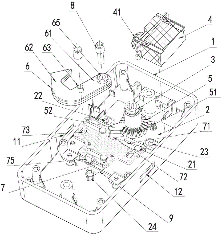
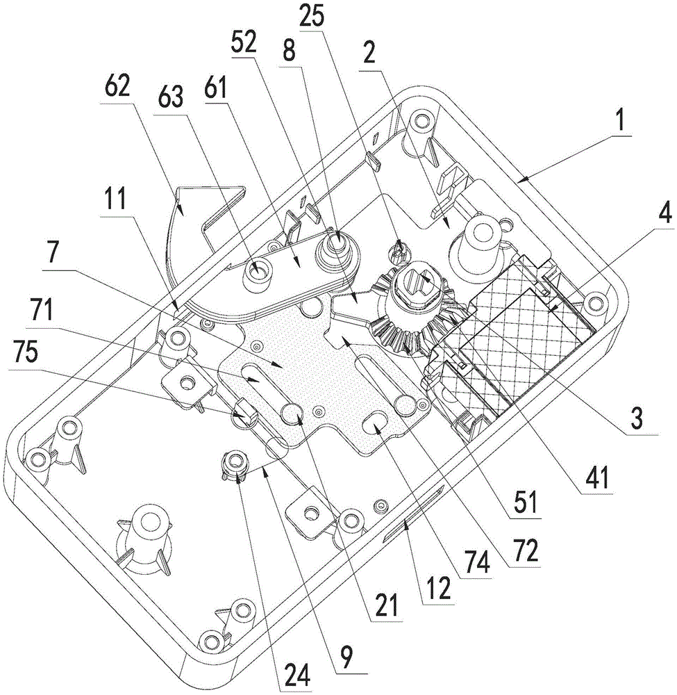
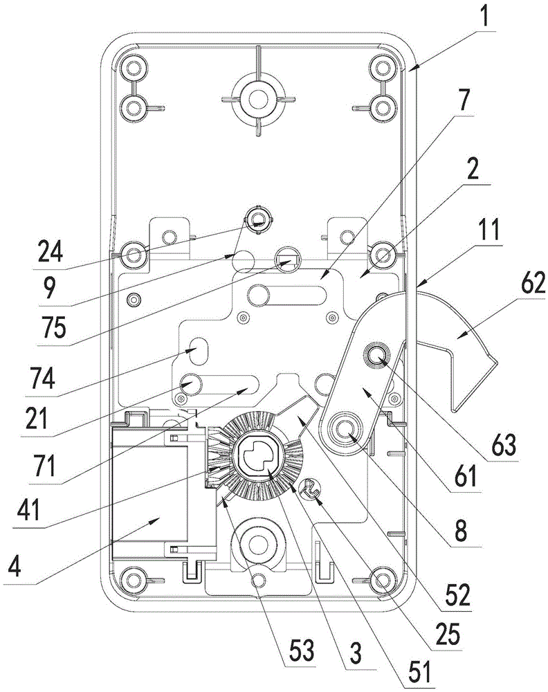
[0037] Such as Figure 1 to Figure 6 As shown, the door lock device that can be controlled manually or electrically in this embodiment includes an outer panel 1, an inner panel 2, a handle shaft 3, a motor 4, a handle interlocking block 5, a dead bolt 6 and a dead bolt pushing slider 7 .

[0038] A first lock tongue 11 and a second lock tongue 12 are respectively provided on two sides of the outer panel 1 .

[0039] Inner panel 2...


PUM


Abstract

The invention provides a manually controlled or electrically controlled door locking device which comprises an outer panel, an inner panel, a handle rotating shaft, a motor, a handle linkage block, a lock tongue and a lock tongue pushing sliding block, wherein a driving gear is arranged on a rotating shaft of the motor; a driven gear disc is arranged on the handle linkage block; a sliding block poke rod capable of poking the lock tongue pushing sliding block to move relative to the inner panel is arranged on the handle linkage block as well; and the lock tongue pushing sliding block is connected with the lock tongue. According to the door locking device, the motor can sequentially drive the driving gear, the driven gear disc, the sliding block poke rod, the lock tongue pushing sliding block and the lock tongue to achieve the telescopic motion of the lock tongue; the handle rotating shaft, the handle linkage block, the sliding block poke rod, the lock tongue pushing sliding block and the lock tongue can be sequentially driven to achieve the telescopic motion of the lock tongue through controlling a handle; and the door locking device has the advantages that the structure is simple, manual or electrical controlled double drive is achieved, the structure design is reasonable, the burglary prevention function is better, and the like.

Description

technical field [0001] The invention relates to a lock, in particular to a door lock device with simple structure, which can be switched manually or electrically controlled. Background technique [0002] Electric control locks have been widely used in many occasions due to their advantages of intelligence and convenience. [0003] There are mainly two types of electronically controlled locks commonly used in the market: one is that the signal sensor transmits instructions to the circuit board by sensing signals such as fingerprints or passwords, and drives the motor to open. The motor is connected to the clutch or the deadbolt block through the gear set. The start-up of the motor will directly drive the deadbolt to extend or retract into the lock housing to achieve the purpose of locking or unlocking. The other is to drive the motor through the handle. The rotating shaft of the handle is provided with a motor-driven dial, and the motor is also provided with a motor-driven c...

Claims


Application Information

Patent Timeline
Patent Type & Authority Applications(China)
IPC IPC(8): E05B47/00E05B3/00E05B15/00E05B15/10E05B15/04E05B63/04
CPCE05B3/00E05B15/00E05B15/04E05B15/10E05B47/0012E05B63/04
Inventor 胡昌阵
Owner 佛山市思歌锁业科技有限公司
Why Eureka
Try Eureka