
Self-centering clamping device for shaft tube parts

A self-centering clamping and parts technology, applied in positioning devices, metal processing machinery parts, clamping, etc., can solve problems such as structural space restrictions, complex mechanical structures, and unbalanced loads in the force transmission process, and achieve stable driving pressure. High degree of automation, avoiding the effect of clamping eccentricity

Inactive Publication Date: 2017-11-17
HEFEI PRESSURE MACHINERY
View PDF11 Cites 1 Cited by
  • Summary
  • Abstract
  • Description
  • Claims
  • Application Information

AI Technical Summary

Problems solved by technology

[0002] The existing self-centering clamping methods for shaft and tube parts are: (1) Servo type, the cost is too high; (2) Pneumatic type, the clamping force is small and limited by the structural space; (3) Gear teeth Bar type, complex mechanical structure, often produces partial load in the process of force transmission

Method used


Image

  • Self-centering clamping device for shaft tube parts
  • Self-centering clamping device for shaft tube parts

Examples


Embodiment Construction

[0026] The embodiments of the present invention will be described in detail below. This embodiment is implemented on the premise of the technical solution of the present invention. Detailed implementation modes and specific operation procedures are given, but the protection scope of the present invention is not limited to the following implementations. example.

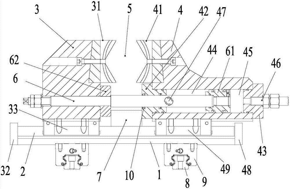
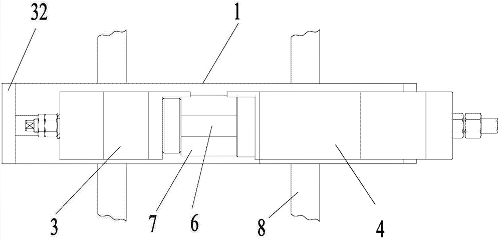
[0027] See figure 1 , figure 2 The self-centering clamping device for shaft and tube parts provided in this embodiment includes a worktable 1 on which a first linear guide rail 2 extending in the left-right direction is provided, and the guide rail is slidably provided with The left cylinder block 3 and the right cylinder block 4 are arranged side by side. The left cylinder block 3 and the right cylinder block 4 are provided with a left clamping claw 31 and a right clamping claw 41 corresponding to the upper part of the opposite side. The claw 31 and the right clamping claw 41 together form a clamping channel 5 for cla...


PUM


Abstract

The invention discloses a self-centering clamping device of axle tube type parts. A first linear guide rail is arranged on a worktable; a left cylinder body and a right cylinder body are arranged on the guide rail in a sliding manner; a left clamping claw and a right clamping claw are arranged at the upper parts of relative sides of the left cylinder body and the right cylinder body; a piston rod penetrates through the lower parts of the left cylinder body and the right cylinder body along a left-right direction; a right channel through which the piston rod passes is formed in the lower part of the right cylinder body; a sealed cavity is formed by blocking the left and right ends of the right channel; a piston head is fixedly arranged at the right end of the piston rod; the piston head is located in the sealed cavity of the right cylinder body and can move in the sealed cavity from left to right; and the left part of the piston rod is fixedly connected with the left cylinder body. The self-centering clamping device of the axle tube type parts has the advantages that self-centering clamping work of the axle tube type parts can be realized, a whole process is automatic, the self-centering clamping stability is high, clamping pressure is stable, the fluctuation is small and a pressure adjustable range is large.

Description

Technical field [0001] The invention relates to a self-centering clamping device for shaft and tube parts. Background technique [0002] The self-centering clamping of existing shaft and tube parts generally adopts the following methods: (1) Servo type, which is too costly; (2) Pneumatic type, with small clamping force and limited by structural space; (3) Gear teeth Strip type, complex mechanical structure, tend to produce partial load in the process of force transmission. Summary of the invention [0003] The purpose of the present invention is to overcome the shortcomings of the prior art and provide a self-centering clamping device for shaft and tube parts, so as to achieve high self-centering and clamping stability of shaft and tube parts, stable pressure and small fluctuations. The purpose of large adjustable pressure range. [0004] The present invention is realized through the following technical solutions: [0005] A self-centering clamping device for shaft and tube parts, ...

Claims


Application Information

Patent Timeline
Patent Type & Authority Patents(China)
IPC IPC(8): B23Q3/08
CPCB23Q3/064B23Q3/082
Inventor 张宝车光群
Owner HEFEI PRESSURE MACHINERY
Learn More