Energy-saving environment-friendly air supply branch pipe

An energy-saving and environmental-friendly technology with branch pipes, applied in blast furnace details, furnace types, blast furnace parts, etc., can solve problems such as energy waste, large energy waste, cracks in refractory materials, etc., to improve the operating environment, reduce pollution emissions, and increase hot air temperature Effect

Inactive Publication Date: 2016-04-20
TANGSHAN JINSHAN TENGYU SCI & TECH
View PDF5 Cites 2 Cited by
  • Summary
  • Abstract
  • Description
  • Claims
  • Application Information

AI Technical Summary

Problems solved by technology

[0003] At present, there is a phenomenon of uneven distribution of hot air in the air supply branch pipes of domestic blast furnaces, which leads to unstable internal working conditions of blast furnaces, resulting in large energy waste and low production capacity.
[0004] The commonly used air supply branch pipe with double-layer shell can improve the process of the current ironmaking industry, increase production capacity, and continuously increase the wind temperature, wind pressure, and oxygen enrichment. Although compared with the performance of the previous air supply branch pipe, it has obvious Progress, but due to design flaws, the refractory material cracks under the action of stress, resulting in frequent accidents such as high surface temperature, redness, and burn-through of the air supply branch pipe, resulting in frequent temporary shutdown of the blast furnace for maintenance, resulting in energy waste and production decline , poor working environment
The existing air supply branch pipe structure can no longer meet the current production process requirements of high air temperature, high air pressure, and large oxygen enrichment

Method used


Image

  • Energy-saving environment-friendly air supply branch pipe
  • Energy-saving environment-friendly air supply branch pipe
  • Energy-saving environment-friendly air supply branch pipe

Examples


Embodiment Construction

[0022] The present invention will be further described below in conjunction with the embodiments given in the drawings, but the embodiments do not constitute any limitation to the present invention.

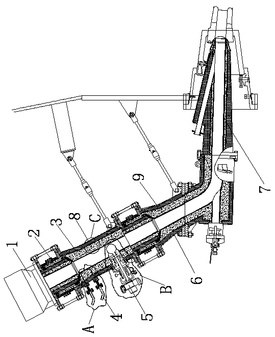
[0023] See figure 1 , Energy-saving and environmentally-friendly air supply branch pipe, composed of gooseneck 1, compensator 2, middle section 3, lower section 6, and straight blown pipe 7. Among them, two compensators 2 are installed, one is set in gooseneck 1 and middle section 3. The other is set between the middle section 3 and the lower section 6; the middle section 3 is equipped with a pressure measuring device 4 and a flow regulating device 5; the inner side of the metal steel shell 9 of the air supply branch pipe is provided with a multiple thermal insulation structure 8 .

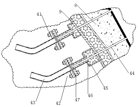
[0024] See figure 2 , The pressure measuring device 4 consists of two upper pressure measuring tubes 41 and lower pressure measuring tubes 42; the upper pressure measuring tube 41 and the lower pressure ...


PUM


Abstract

The invention relates to a blast furnace air supply pipeline, in particular to an energy-saving environment-friendly air supply branch pipe. The energy-saving environment-friendly air supply branch pipe comprises a gooseneck, a compensator, a middle segment, a lower segment, and a straight blow pipe, wherein a piezometric pipe used for measuring temperature, pressure and volume of hot wind in the air supply branch pipe and a flow control valve used for adjusting the pressure of the wind in the air supply branch pipe are mounted in the middle segment; a multiple heat-insulating thermal insulation structure is arranged on the inner side of the metal steel shell of the air supply branch pipe. Due to flow rate and wind pressure adjustment, hot wind parameters of all air supply branch pipes can be consistent, so that smelting efficiency and molten iron quality of a blast furnace can be improved greatly, and energy consumption can be reduced; due to the multiple heat-insulating thermal insulation structure, temperature on the outer surface of each air supply branch pipe can be lowered effectively, temperature of hot wind sent into the blast furnace is raised, the operation environment is improved, and non-renewable energy is saved.

Description

Technical field [0001] The invention relates to a blast furnace air supply pipe, in particular to an energy-saving and environment-friendly air supply branch pipe. Background technique [0002] The blast furnace hot air in the iron and steel industry is sent into the blast furnace by the hot blast furnace, through the hot blast main pipe and the surrounding pipe, through the blast furnace air supply branch pipe. [0003] At present, the domestic blast furnace air supply branch pipes have uneven distribution of hot air, which leads to unstable internal working conditions of the blast furnace, resulting in large energy waste and low production capacity. [0004] The commonly used air supply branch pipes with double-layer shells are useful for improving the current ironmaking industry's technology, increasing production capacity, and continuously increasing air temperature, air pressure, and oxygen enrichment, although the performance of the previous air supply branch pipes has been sig...

Claims


Application Information

Patent Timeline
Patent Type & Authority Applications(China)
IPC IPC(8): C21B9/10
CPCC21B9/10
Inventor 田建全
Owner TANGSHAN JINSHAN TENGYU SCI & TECH
Why Eureka
Try Eureka